Method of imaging an object for tracking and documentation in transportation and storage

a technology of object tracking and documentation, applied in the field of producing images, can solve the problems of object loss or damage in transport, overcharging or undercharging a customer, and not being suitable for the purpose of tracking objects in transport, so as to reduce the size of the image file, without the cost and complexity of additional hardware

Active Publication Date: 2019-07-02
METTLER TOLEDO GMBH
View PDF18 Cites 1 Cited by
  • Summary
  • Abstract
  • Description
  • Claims
  • Application Information

AI Technical Summary

Benefits of technology

[0024]The three-dimensional model can be rotated in order to produce a two-dimensional image of the object surface as seen from any desired viewing angle that was exposed to the scanner rays. The method has the advantage that it uses an existing dimensioning system rather than requiring a plurality of cameras that would have to be installed in different locations in order to capture the entire surface of the object in two-dimensional images. The method thus adds an imaging function to existing dimensioning systems without the cost and complexity of additional hardware.
[0025]The method can further include a step in which any points that are not part of the object of interest are removed from the three-dimensional model. This not only reduces the image file size, but also avoids revealing any aspects of the operating environment in which the dimensioning and imaging of the object took place, such as the personnel, equipment and procedures involved in handling the object.

Problems solved by technology

Objects can be lost or damaged in transport.
However, in large-scale facilities where many shipments are processed at a fast pace and out of sight of the customer, such manual methods are error-prone and can result in either overcharging or undercharging a customer.
The system proposed in U.S. Pat. No. 7,215,430 B1, which generates an image of a stationary target object from a single perspective, is however not suitable for the purpose of tracking objects in transport, as the objects usually present themselves randomly at different viewing angles.

Method used


Image

  • Method of imaging an object for tracking and documentation in transportation and storage
  • Method of imaging an object for tracking and documentation in transportation and storage
  • Method of imaging an object for tracking and documentation in transportation and storage

Examples


Embodiment Construction

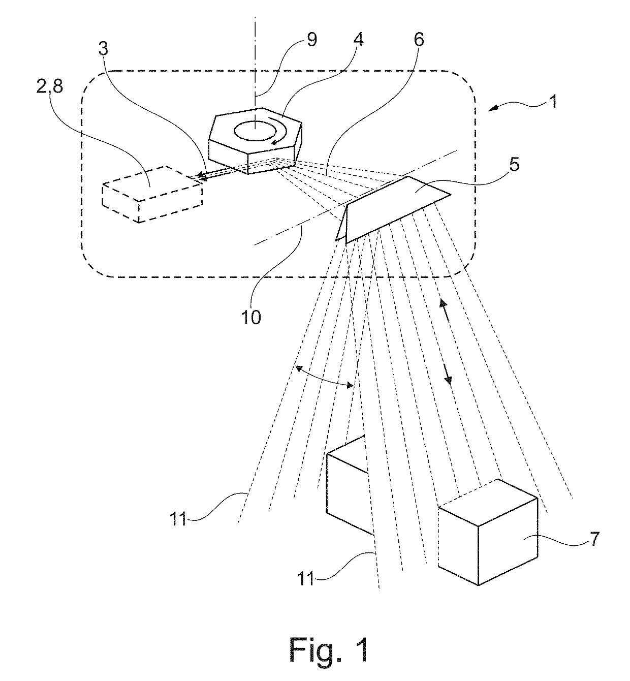
[0045]FIG. 1 schematically illustrates a laser scanner 1 of a type that can be used to carry out the method of the present invention. Its principal components are an emitter 2 of a collimated beam 3 of modulated laser radiation, a dynamic beam deflector 4, 5 to move the collimated beam 3 in fan-shaped sweeps 6 over the object 7 (wherein the latter can be at rest or in motion), and a radiation sensor 8 (arranged here in a combined emitter / receiver unit 2, 8) to receive the radiation reflected from the object 7 and convert it into an electrical signal.

[0046]After leaving the emitter 2, the laser beam 3 meets the hexagonal mirror prism 4 which in the arrangement of FIG. 1 rotates about a vertical axis 9 and causes the laser beam 3 to perform continuous fan-like sweeps in a horizontal plane. A second deflector 5, here in the form of a planar mirror 5 swiveling about a horizontal axis 10 deflects the sweeping laser beam 3 into the area of the object 7. As a result of the swivel movement ...


PUM


Abstract

In a method of operating a dimensioning system with a plurality of laser scanners, a processor controls the operations of the scanners and processes the scanner signals, and further with memory for storing data delivered by the processor, the data acquired by the dimensioning system in its regular mode of operation are used to construct a three-dimensional model of surface points of the object including spatial coordinates and image intensity for each surface point. The three-dimensional model is stored in the memory. Based on the three-dimensional model, two-dimensional images from any desired viewing angle that was exposed to the scanner rays can be produced on demand to document the appearance of the object at the time the scan was taken.

Description

CROSS-REFERENCE TO RELATED APPLICATIONS[0001]This application is entitled to benefit of a right of priority from European Patent Application No. 16154189.1, filed on 4 Feb. 2016. The content of that application is incorporated by reference as if fully recited herein.TECHNICAL FIELD[0002]The invention relates to a method of producing images of cargo objects, such as packages, crates and pallets, by employing previously unused capabilities of dimensioning systems. The term “dimensioning” in the present context refers to the process of determining the volume that an object occupies in order to assess shipping and storage charges. A dimensioning system is an apparatus that performs this dimensioning process automatically.BACKGROUND OF THE ART[0003]The concept of dimensioning stems from the thought that shipping charges should not be determined solely based on the weight of an object, but also based on its dimensions, to account for the amount of space taken up in a warehouse or on a tra...

Claims


Application Information

Patent Timeline
Patent Type & Authority Patents(United States)
IPC IPC(8): G01C3/00G01C7/00G01V8/26G01B11/00G01B11/02G01B11/03G01B11/04G01B11/06G01B11/24G01B11/25G01S17/87
CPCG01B11/026G01B11/005G01B11/02G01B11/03G01B11/04G01B11/06G01B11/0691G01B11/24G01B11/2527G01C3/00G01C7/00G01V8/26G01B11/002B65G2203/044B65G2203/0208B65G2203/0225B65G2203/0258G01B11/00G01S17/42G01S17/87G01B11/245G01B11/2518G01S7/4808G01B11/2522B65G2203/042
Inventor SORENSEN, EINARRUTGER, ESPEN
Owner METTLER TOLEDO GMBH
Why Eureka
Try Eureka