Spinal multi-level intersegmental stabilization system and method for implanting

Inactive Publication Date: 2019-03-07
LINKSPINE INC
View PDF2 Cites 10 Cited by
  • Summary
  • Abstract
  • Description
  • Claims
  • Application Information

AI Technical Summary

Benefits of technology

[0028]By this method, the implant as described above can be implanted. Additionally, this method requires a minimum size for the access hole only, thereby keeping the surgery wound small and aiding in fast recovery of the patient. The minimum size access hole is a particular advantage if the connecting member is configured such as to span over at least one intermediate vertebra.
[0029]Preferably, the transfacetal fastening means and the second fastening means are angled such that their tips diverge by an angle of at least 30°. Such a rather high diversion angle ensures that the opposite ends will be positioned in close proximity to each other. This is important since any tools for engaging the fastening means will be applied there. Hence, the tool access area is rather confined. Conventionally, in such a scenario a rather large access hole would be required, its size mirroring the combined height of the vertebrae concerned. According to the inventive method, this size can be reduced considerably about the height of one or two vertebra. As a result

Problems solved by technology

The wear of the articulated connection (facet joints) of two neighbouring vertebrae may lead to a restricted movement, pain or even loss of mobility.
However, this known fusion implant requires a relatively strong and intact bone structure of the vertebral body.
Quite often the adjacent structure is not strong enough.
In such a case further stabilization is requi

Method used


Image

  • Spinal multi-level intersegmental stabilization system and method for implanting
  • Spinal multi-level intersegmental stabilization system and method for implanting
  • Spinal multi-level intersegmental stabilization system and method for implanting

Examples


Embodiment Construction

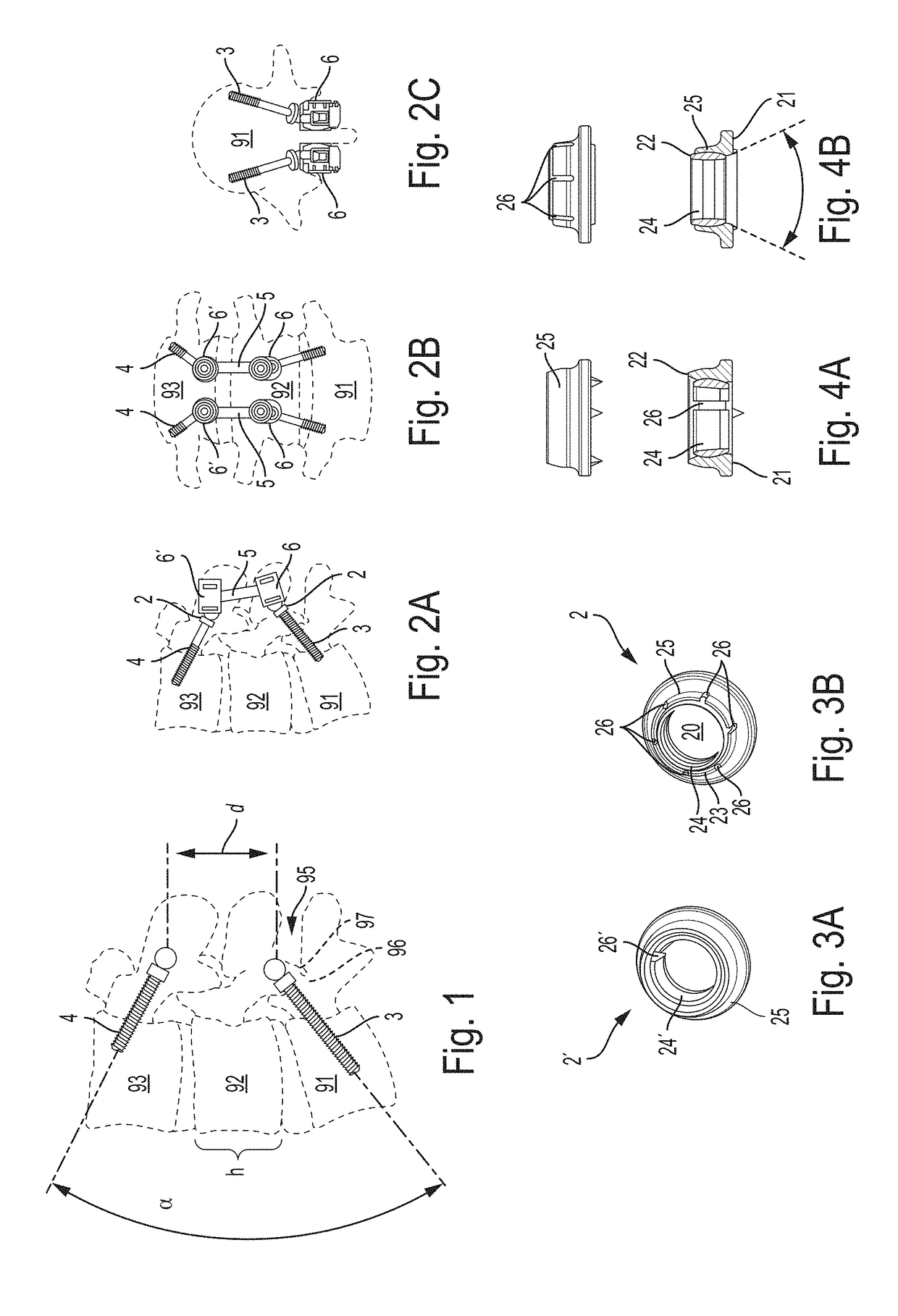
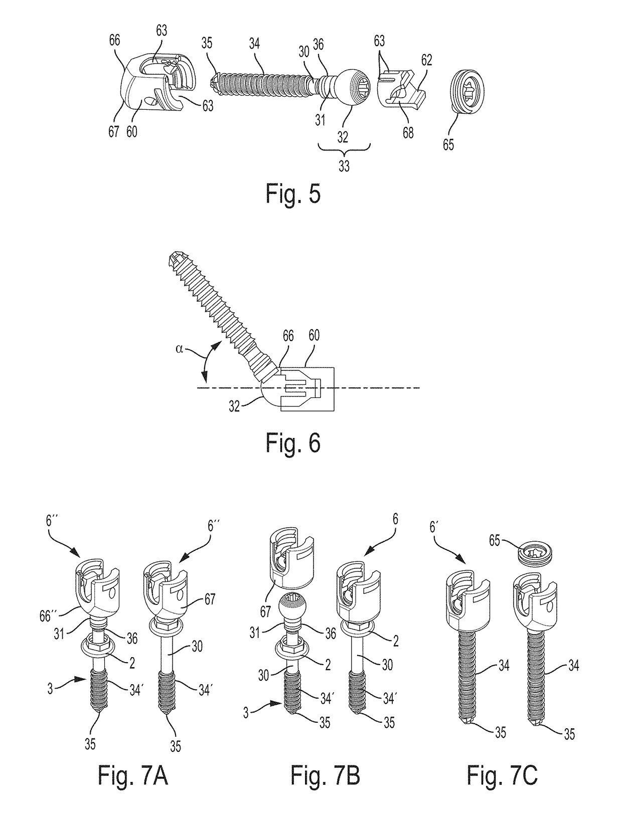
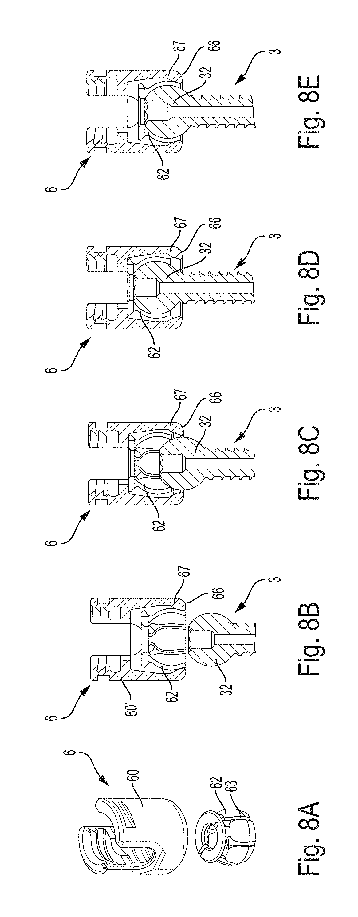
[0041]An embodiment of a fusion implant 1 comprises a lower and upper retainer module 6, 6′ and an elongated carrier element 5. In the lower retainer module 6, a transfacetal fastening means 3 is held. In the upper retainer module 6′, a second fastening means 4 is held. Further, a washer 2 is provided through which the screw 30 is routed. As it can be readily appreciated in the drawing of FIG. 1, the transfacetal fastening means 3 and second fastening means 4 are diverging at an angle α (the retainer modules 6, 6′ and the elongated carrier element 5 are omitted in FIG. 1 for clarity). Thereby, the heads of the transfacetal fastening means 3 and second fastening means 4 are located in close proximity (much closer than the positioning of the transfacetal fastening means 3 and second fastening means 4 at the vertebrae themselves), so that a rather small access hole will suffice. A small access hole means a small surgery wound and therefore lesser stress for the patient.

[0042]The transf...


PUM


Abstract

A multi-level intersegmental stabilization implant for a facet joint of a first vertebra includes a lower retainer module having a transfacetal fastener and an upper retainer module having a second fastener configured for fastening through the pedicle of an upper vertebra. The lower and upper retainer modules are connected by an elongated carrier element dimensioned such as to span across at least two vertebrae. The transfacetal fastener is configured as a screw having a head and a shaft ending with a tip, the shaft being provided with a thread at least in a region near its tip such that it engages exclusively the lower section of the facet joint, wherein a washer is provided co-operatively connected with the transfacetal fastener, the washer being configured for bearing on an outer surface of the upper section of the facet joint.

Description

CROSS-REFERENCE TO RELATED APPLICATIONS[0001]This application is a national stage application under 35 USC 371 of International Application no. PCT / US2016 / 056290 filed Oct. 10, 2016, which claims priority to U.S. Provisional Patent Application No. 62 / 239,766, filed Oct. 9, 2015, the entire contents of each of which are incorporated herein by reference in its entirety.FIELD OF INVENTION[0002]The invention relates to a spinal stabilization system and implanting method for multilevel intersegmental application.BACKGROUND OF THE INVENTION[0003]In the human body, the spinal column is a structural element of the human skeleton. It is comprised of a plurality of articulating vertebrae, which are arranged one above another divided by intervertebral discs. The discs allow for transfer of load between the vertebrae while the facet joints are the structure that connects the vertebrae one to another. Each vertebra has two sets of facet joints. One pair faces upward (superior articular facet) an...

Claims


Application Information

Patent Timeline
IPC IPC(8): A61B17/70
CPCA61B17/7064A61B17/7044A61B17/701A61B17/7037A61F2/4405A61B17/7043
Inventor CHAPUT, CHRISTOPHER D.
Owner LINKSPINE INC
Why Eureka
Try Eureka