Electronically controlled mechanical resistance device for rowing machines

a technology of mechanical resistance and rowing machine, which is applied in the field of rowing machines, can solve problems such as backlash, and achieve the effect of removing backlash

Active Publication Date: 2019-03-07
JEREMIC BOJAN
View PDF0 Cites 12 Cited by
  • Summary
  • Abstract
  • Description
  • Claims
  • Application Information

AI Technical Summary

Benefits of technology

[0008]The primary goal of this invention is to eliminate the backlash that exists when exercising on state of the art rowing machines. This backlash is present between the idle and the power phases of rowing strokes and occurs on any common rowing machine that comprises a flywheel. It is hoped that this invention is used to substitute the flywheel integrated with other mechanical resistance means with a device comprising an electric motor / generator or a solenoid and a programmable control means.
[0009]By eliminating the backlash occurring on commonly used rowing machines, this invention allows the rowers to execute stress free rowing strokes. Stress free rowing leads to achieving better rowing technique, which translates to faster moving boats. Most importantly, better rowing technique contributes to significantly reducing the potential for rowers to sustain motion related injuries.

Problems solved by technology

This backlash is present between the idle and the power phases of rowing strokes and occurs on any common rowing machine that comprises a flywheel.

Method used


Image

  • Electronically controlled mechanical resistance device for rowing machines
  • Electronically controlled mechanical resistance device for rowing machines
  • Electronically controlled mechanical resistance device for rowing machines

Examples


Embodiment Construction

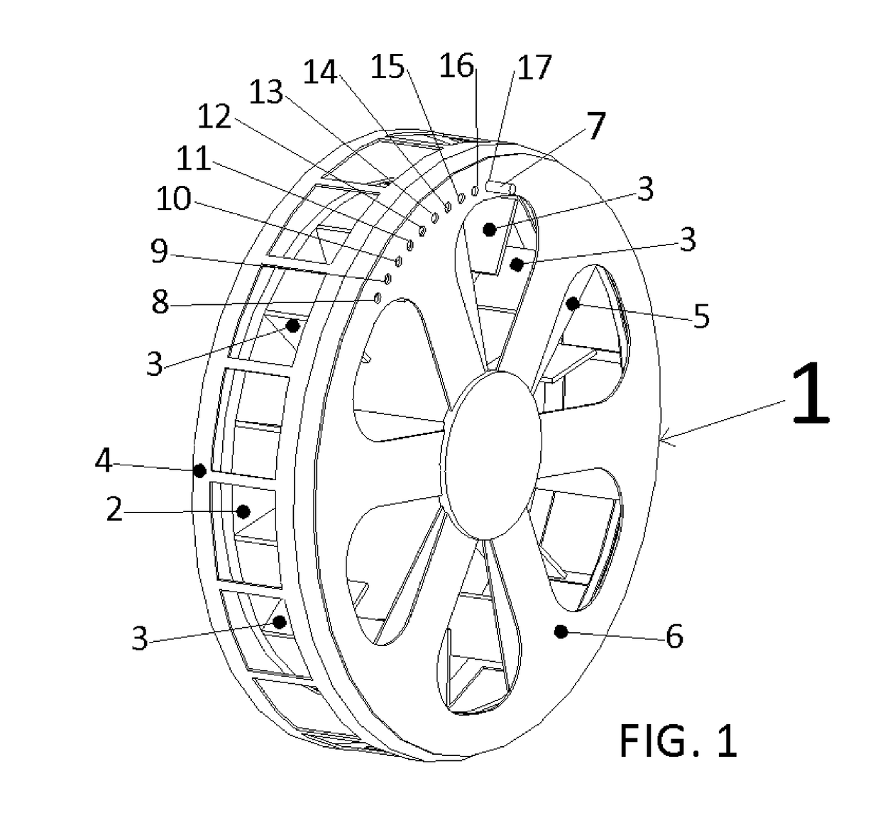
[0021]This invention is intended to replace a common mechanical resistance device on rowing machines. An example of a prior art device is shown in FIG. 1, where system 1 is an air pump. The rotating parts comprise the flywheel 2 and a multitude of air peddling vanes 3, perpendicularly disposed and rigidly affixed to the flywheel's largest surface. The mechanism also includes a valve, comprising the stationary and the adjustable components. The stationary components of the valve are the safety shroud 4 and the face plate 5. Together, they envelop the rotating pump parts, forming a cavity in which the air peddling vanes 3 move the air as the flywheel rotates. The face plate 5 is perforated. It is disposed centered and parallel to the flywheel 2. It also shields the air peddling vanes 3 from accidental contact with objects outside of the pump. Since the valve cover 6 is also perforated, its rotation on top of the perforated faceplate 5 causes different interference openings between the...


PUM


Abstract

This invention offers a rowing machine's mechanical resistance device which comprises an electric motor or a solenoid, a programmable control means and a custom algorithm, controlling the programmable controls means. It eliminates the compromising effect of backlash between the rower's handle and the resistance imparting device. This backlash is present between the power and the idle phases of rowing strokes on all state of the art rowing machines comprising flywheels. Ultimately, this invention allows all rowers to improve their rowing form and avoid injury.

Description

FIELD OF THE INVENTION[0001]The invention relates to the field of exercise equipment and more specifically to rowing machines.BACKGROUND[0002]Most state-of-the-art rowing machines allow oarsmen to simulate motions comparable to ones found when rowing in racing shells. To impart resistance to the rower's physical effort, some rowing machines deploy hydraulic rams (U.S. Pat. No. 5,104,363). However, the most successful ones, in terms of their ability to simulate rowing in boats, deploy an adjustable fluid pump. In certain embodiments, the pump moves air (U.S. Pat. No. 5,382,210) and in the other, the pump moves liquid water (U.S. Pat. No. 4,884,800). Regardless of the type of fluid, all said pumps comprise flywheels. The purpose of moving a fluid through a pump is to simulate an oar drag through water. The purpose of the integrated flywheel is to simulate a boat's inertia.[0003]The beneficial effects of deploying flywheels on rowing machines relate to the flywheel absorbing the user's...

Claims


Application Information

Patent Timeline
Patent Type & Authority Applications(United States)
IPC IPC(8): A63B21/005
CPCA63B21/0058A63B21/0054A63B22/0076A63B21/0053A63B21/153A63B21/157A63B24/0087A63B2022/0084A63B2024/0093A63B21/0059A63B21/005A63B21/0057A63B2022/0079A63B21/0055
Inventor JEREMIC, BOJAN R.NAZARIAN, HRAYR
Owner JEREMIC BOJAN
Why Eureka
Try Eureka