X-ray generator

Active Publication Date: 2019-03-07
RIGAKU CORP
View PDF4 Cites 2 Cited by
  • Summary
  • Abstract
  • Description
  • Claims
  • Application Information

AI Technical Summary

Benefits of technology

[0016]Through the present invention, the target and the separator rotate together in the same direction, and there is therefore no difference in speed of the water between the inner surface of the target and the outer surface of the separator in a cooling region. Th

Problems solved by technology

However, in the X-ray generator disclosed in Patent Citation 1, because of the large difference in speed between the coolant on the inner surface of the target and the coolant on the outer surface of the separator, the problem arises that a drive

Method used


Image

  • X-ray generator
  • X-ray generator
  • X-ray generator

Examples


first embodiment

of X-ray Generator

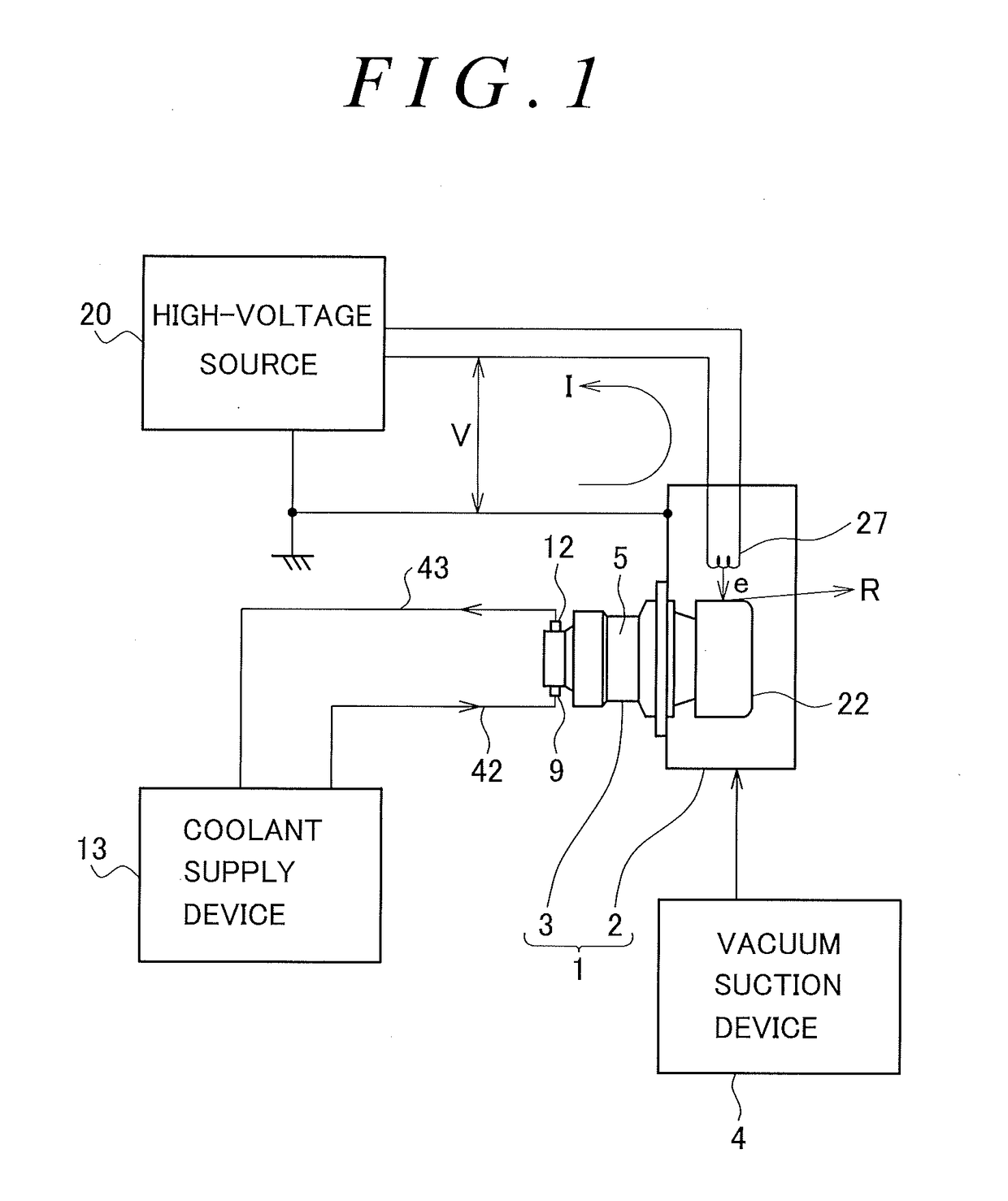
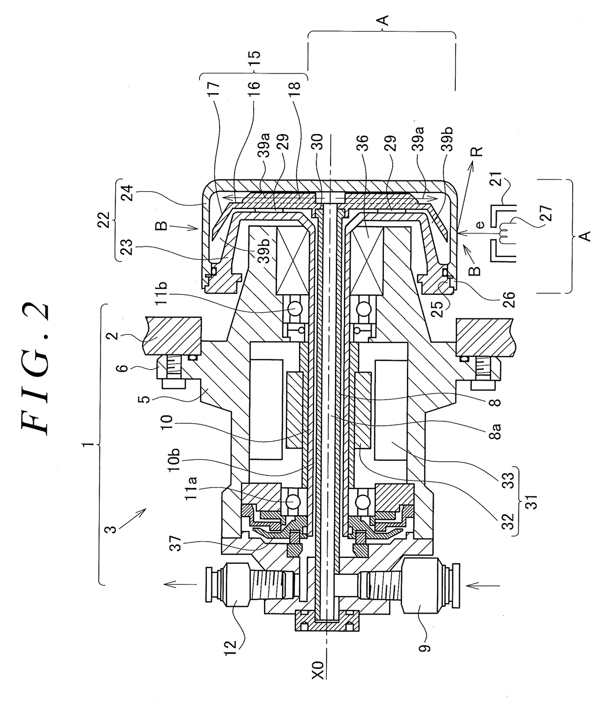
[0030]FIG. 1 is a diagram illustrating the overall structure of an embodiment of the X-ray generator according to the present invention. An X-ray generator 1 in FIG. 1 has a vacuum container 2 and an anode assembly 3. A vacuum state is maintained inside the vacuum container 2 by a vacuum suction device 4. In FIG. 2, the anode assembly 3 has a generally cylindrical casing 5. A flange 6 provided to the casing 5 is fixed to the vacuum container 2.

[0031]An inner tube 8 is provided in a center part of the inside of the casing 5. The inner tube 8 is a hollow cylindrical tube. The inner tube 8 is fixed to a left end part of the casing 5, and extends along the center axis X0 of the casing 5. The inner tube 8 is fixed in a state of neither rotating nor changing position. A hollow part of the inner tube 8 functions as a coolant inflow path 8a. A left end part of the coolant inflow path 8a is connected to an inlet fitting 9. The inlet fitting 9 is connected to a coolant suppl...

second embodiment

of the X-ray Generator

[0047]FIG. 8 illustrates the cross-sectional structure of a main part of another embodiment of the X-ray generator according to the present invention. In FIG. 8, a modification is added to the structure of the first embodiment illustrated in FIG. 7. Aspects of the structure of the present embodiment other than the structure illustrated in FIG. 8 are the same as in the first embodiment.

[0048]In the present embodiment, formation of the gap 30 between the expanded part 8b of the distal end of the inner tube 8 and the wall of the recess 19 of the separator 15 is the same as in the previously described embodiment illustrated in FIG. 7. It was described in the previous embodiment that cooling water as the coolant is supplied to the cooling region B in FIG. 2, and the to-be-cooled surface C including the X-ray focus in FIG. 6 is cooled. It was also described that a gap 30 is provided between the expanded part 8b of the distal end of the inner tube 8 and the wall of th...

third embodiment

of the X-ray Generator

[0051]FIG. 9 illustrates the cross-sectional structure of a main part of yet another embodiment of the X-ray generator according to the present invention. In FIG. 9, a modification is added to the structure of the second embodiment illustrated in FIG. 8. Aspects of the structure of the present embodiment other than the structure illustrated in FIG. 9 are the same as in the first embodiment.

[0052]In FIG. 9, the diameter of a first opening as an end opening on a small-area side of the tapered tube 44 is designated as D1, and the diameter of a second opening as an opening for receiving the cooling water exiting the opening of the tapered tube 44 is designated as D2. The expression

T=Q2 / Q1

is the cooling water shortcut rate, where Q1is the total amount of cooling water flowing through the inner tube 8, and Q2 is the amount of cooling water flowing into the gap 30. In the present embodiment, the condition

1.2D1≤D2≤1.27D1

is set, and the shortcut rate T is kept to a smal...


PUM


Abstract

An X-ray generator comprising a target for receiving electrons and generating X-rays, a separator for dividing an internal space of the target into a coolant inflow path and a coolant outflow path, a motor for rotating the target, and a coolant inflow path and a coolant outflow path for supplying a coolant to the coolant inflow path and recovering the coolant through the coolant outflow path, wherein the separator rotates in the same rotation direction as the target when the target rotates. In the X-ray generator in which a coolant inflow path and a coolant outflow path are provided by a separator inside a rotating target, reduced torque load and reduced vibration can be realized.

Description

BACKGROUND OF THE INVENTIONField of the Invention[0001]The present invention relates to an X-ray generator in which a coolant such as water is circulated inside a rotating anode so as to cool the rotating anode. The present invention particularly relates to an X-ray generator in which a separator is provided inside the rotating anode, and a coolant inflow path and a coolant outflow path are thereby provided inside the rotating anode.Description of the Related Art[0002]A conventional X-ray generator is disclosed in JP-A 2006-179240 (Patent Citation 1). In this conventional X-ray generator, a partition pipe as an inner cylinder and a rotary shaft as an outer cylinder are provided coaxially. The partition pipe and the rotary shaft are both hollow cylinders. A separator is attached to the distal end of the partition pipe. A target is attached to the distal end of the rotary shaft. The separator is housed in the target.[0003]When electrons impinge on the target, X-rays are emitted from t...

Claims


Application Information

Patent Timeline
IPC IPC(8): H01J35/10
CPCH01J35/106H01J2235/1262H01J35/08H01J35/26H01J2235/1212
Inventor YAMAKATA, MASAAKICHAKI, TOMOHIROKURIBAYASHI, MASARU
Owner RIGAKU CORP
Why Eureka
Try Eureka