Power cord plug, cable, power cord structure and electrical device

a power cord and plug technology, applied in the field of electric devices, can solve the problems of increasing the overall size affecting the appearance consistency of the household appliance, and not being beautiful or practical, so as to improve the application range of the power cord plug, improve the user experience, and ensure the beauty of the overall appearance.

Inactive Publication Date: 2019-03-07
GUANGDONG MIDEA KITCHEN APPLIANCES MFG CO LTD +1
View PDF18 Cites 1 Cited by
  • Summary
  • Abstract
  • Description
  • Claims
  • Application Information

AI Technical Summary

Benefits of technology

[0018]According to the power cord plug provided by the present disclosure, as the communication device is arranged in the shell of the power cord plug, the communication device can be far away from the electrical device, so the communication ability of the communication device will not be shielded by the metal shell of the electrical device, and will not be affected by a motor, a circuit board, coils, a magnetron and other factors in the electrical device, or affected by the high temperature caused by the operation of the equipment, accordingly the communication device works in a good environment, and the working reliability and stability of the communication device are guaranteed; moreover, the antenna is arranged in the shell and is connected with the communication device for enabling the communication device to receive and send signals, so the connection path between the communication device and the antenna can be shortened, signal transmission is benefited, and the antenna is protected from being damaged easily, thereby improving the working reliability; meanwhile, by means of the inner space of the shell of the power cord plug, no additional size is added to the electrical device, thereby guaranteeing the beauty of the overall appearance, guaranteeing convenience for carrying and improving the user experience.
[0119]In the technical solution, the power cord plug or the power cord structure is applied to the microwave oven, the oven and the water heater, the user can conveniently and remotely control these household appliances, including, but not limited to, opening and closing the household appliances, setting expected values, adjusting operation modes and the like, and can also transmit menus to the microwave oven, the microwave oven and the oven for automatic cooking.

Problems solved by technology

In this manner, the communication device will be shielded by a metal shell of the electrical device and will be interfered by a motor, a circuit board, coils, a magnetron and the like in the household appliance.
In this manner, the communication ability of the communication device will be influenced by the metal shell of the electrical device and will also be affected by the high temperature produced by the electrical device, and this mounting manner will affect the appearance consistency of the household appliance and increase the overall size of the household appliance, thereby being not beautiful or practical.
This manner will affect the appearance consistency of the household appliance, and as the additional antenna portion is increased at the outside of the household appliance, the size of the household appliance is increased, thereby being not beautiful or practical.
Moreover, the antenna mounted at the outside is liable to be damaged.
In summary, due to the existing structure design of the communication device in related art, the communication device is vulnerable to being shielded, vulnerable to high temperature and vulnerable to the interference of other electronic devices, and the appearance consistency of the household appliance is also affected, thereby being not beautiful or practical.

Method used


Image

  • Power cord plug, cable, power cord structure and electrical device
  • Power cord plug, cable, power cord structure and electrical device
  • Power cord plug, cable, power cord structure and electrical device

Examples


eighth embodiment

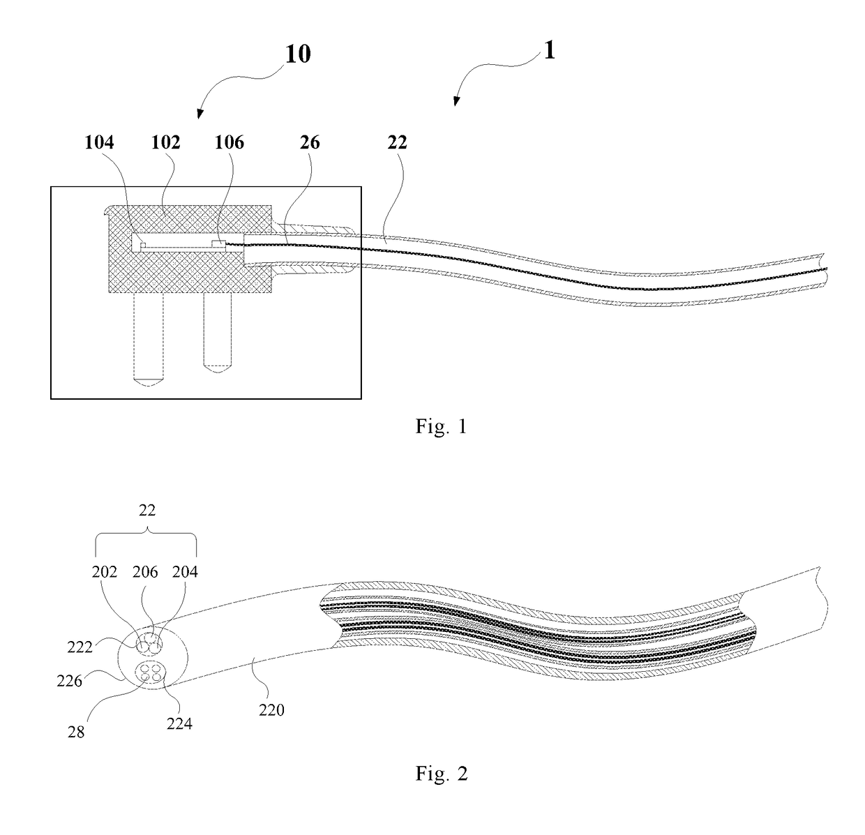
[0207]As shown in FIG. 8, the embodiment of the present disclosure further provides a power cord structure 1 for an electrical device, including: the power cord plug 10 in any one of the above-mentioned technical solutions; a power cord connector 12; and a power cord 22, and one end of the power cord 22 is connected with the power cord plug 10, and the other end of the power cord 22 is connected with the power cord connector 12.

[0208]The power cord structure 1 provided by the embodiment of the eighth embodiment of the present disclosure includes the power cord plug 10 in any one of the above-mentioned technical solutions and the power cord 22 connected with the power cord plug, therefore the power cord structure has all the beneficial effects of the power cord plug 10. The communication device 104 or the antenna 106 is designed on the position of the power cord plug 10, so the problems of shielding, high temperature, interference, beauty and the like of the communication device 104 ...

ninth embodiment

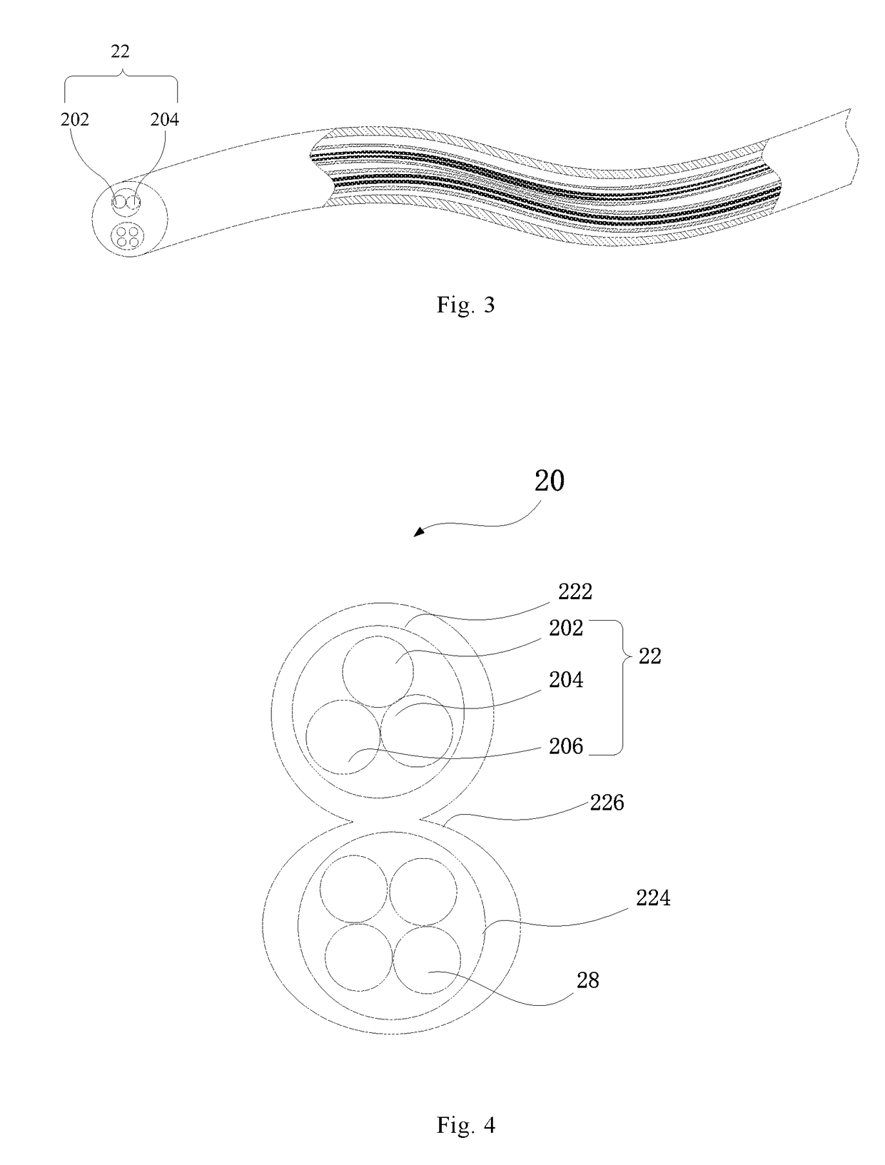
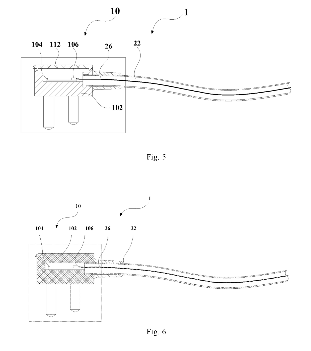
[0215]As shown in FIG. 10 and FIG. 11, the present disclosure provides a power cord structure 1 for an electrical device, including: a power cord plug 10 and a cable 20 component, and the cable 20 component is connected with the power cord plug 10; and, as shown in FIG. 11, the power cord plug 10 includes: a shell 102; a communication device 104 arranged in the shell 102; and a power supply connecting terminal 300 connected with the shell 102 and located below the shell 102, and the shell 102 and the power supply connecting terminal 300 are formed into a rubber power cord plug 10 by injection molding.

[0216]According to the power cord structure 1 provided by the present disclosure, the communication device 104 is arranged in the shell 102 of the power cord plug 10 and is injection molded with the power supply connecting terminal 300 in an overall rubber coating manner, so the power cord plug 10 is of an integrated sealed structure, then the communication device 104 can be far away fr...


PUM


Abstract

The present disclosure provides a power cord plug, a power cord structure and an electrical device for a power cord, and the power cord plug includes: a shell, and a communication device and an antenna arranged in the shell. According to the power cord plug provided by the present disclosure, as the communication device and the antenna are arranged in the shell of the power cord plug, the communication device is far away from the electrical device, so the communication ability of the communication device will not be shielded by the metal shell of the electrical device, and will not be affected by a motor, a circuit board, coils, a magnetron and other factors in the electrical device, or affected by the high temperature caused by the operation of the equipment, accordingly the communication device works in a good environment, and the working reliability and stability of the communication device are guaranteed.

Description

CROSS-REFERENCE TO RELATED APPLICATIONS[0001]This application is a continuation of International Application PCT / CN2017 / 091327, filed on Jul. 14, 2017, which claims the priority of the Chinese Patent Application No. 201620996014.8 entitled “POWER CORD PLUG POWER CORD STRUCTURE AND ELECTRICAL DEVICE”, the Chinese Patent Application No. 201620999746.2 entitled “CABLE, POWER CORD STRUCTURE AND ELECTRICAL DEVICE”, the Chinese Patent Application No. 201620999817.9 entitled “POWER CORD PLUG POWER CORD STRUCTURE AND ELECTRICAL DEVICE”, and the Chinese Patent Application No. 201610773235.3 entitled “POWER CORD PLUG POWER CORD STRUCTURE AND ELECTRICAL DEVICE”, filed in the Chinese Patent Office on Aug. 30, 2016, and the Chinese Patent Application No. 201720705127.2 entitled “POWER CORD STRUCTURE AND ELECTRICAL DEVICE”, filed in the Chinese Patent Office on Jun. 16, 2017, the entire contents of which are herein incorporated by reference.FIELD OF THE DISCLOSURE[0002]The present disclosure rela...

Claims


Application Information

Patent Timeline
Patent Type & Authority Applications(United States)
IPC IPC(8): H01R13/66H01R13/52G08C17/00H01Q1/24
CPCH01R13/665H01R13/5219H01R13/5213G08C17/00H01Q1/24H01R13/504G08C2201/93H01R13/66H01R13/6658H01R24/28
Inventor MA, JIANLIANGZHANG, ZHENFENGLI, SONGTAO
Owner GUANGDONG MIDEA KITCHEN APPLIANCES MFG CO LTD
Why Eureka
Try Eureka