Eureka AIR delivers breakthrough ideas for toughest innovation challenges, trusted by R&D personnel around the world.

Heat dissipation apparatus and communications device

Active Publication Date: 2019-03-07
HUAWEI TECH CO LTD +1
View PDF7 Cites 5 Cited by
  • Summary
  • Abstract
  • Description
  • Claims
  • Application Information

AI Technical Summary

Benefits of technology

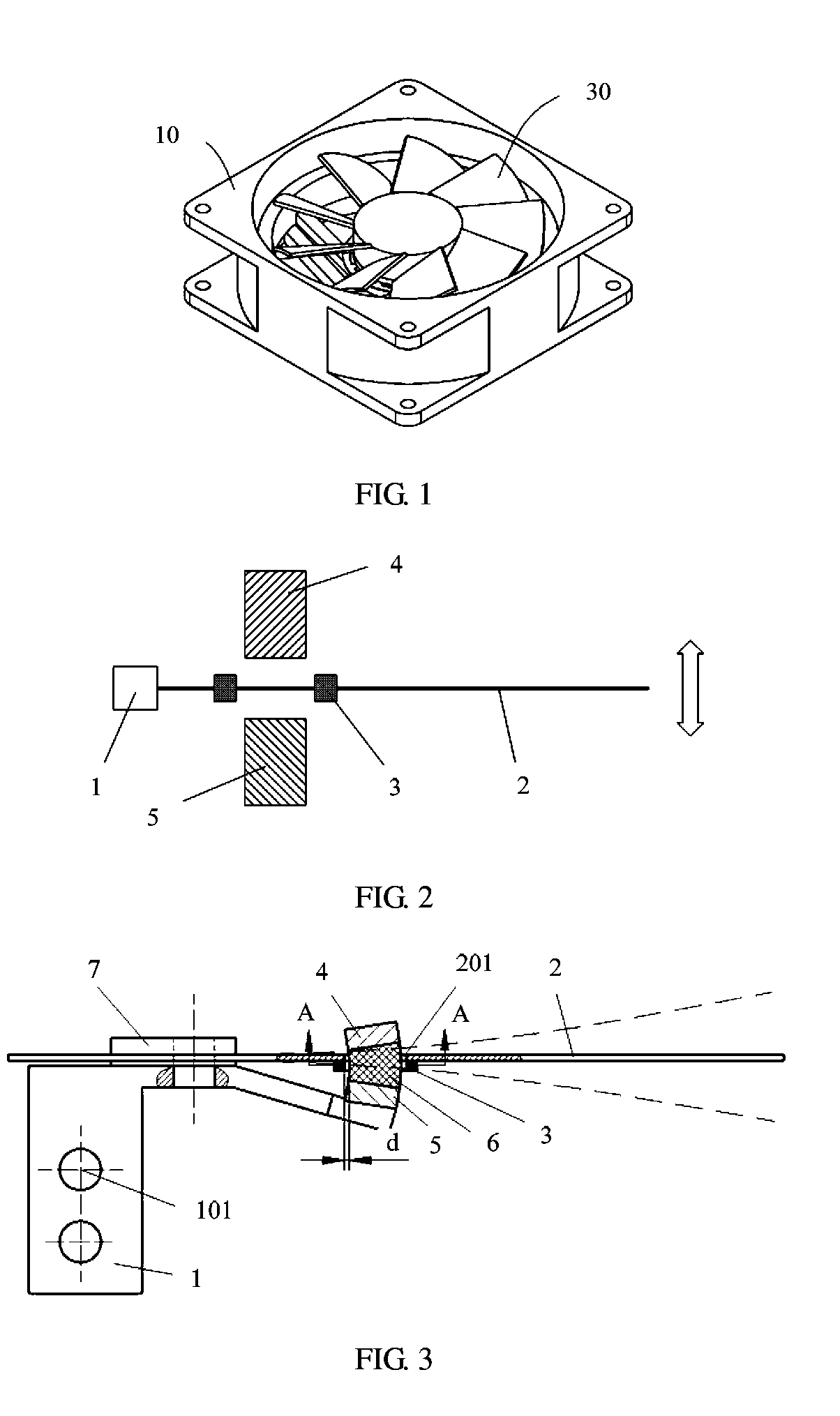
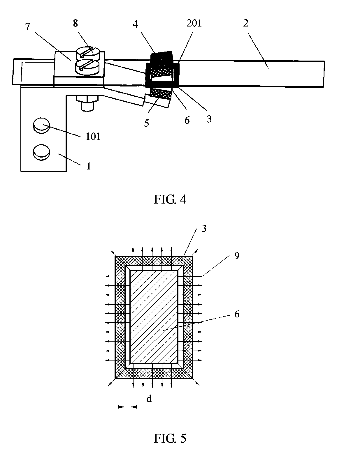
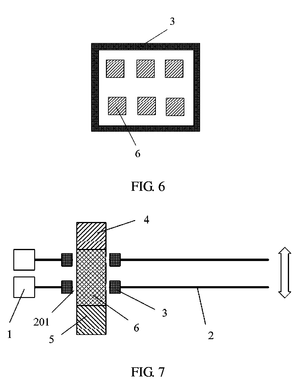
The present invention provides a heat dissipation apparatus and a communications device that can reduce generated noise when heat is dissipated for an electronic component. The heat dissipation apparatus includes a base, a swing plate, and a magnet assembly. The swing plate is fastened to the base, and a loop coil is located between the first magnet and the second magnet. The loop coil is designed to have a magnetic field direction perpendicular to the outer surface of the loop coil, which increases the magnetic force and reduces the likelihood of magnetic field weakening. A magnetic conductive part is also included to adjust the magnetic field distribution and improve the efficiency of the heat dissipation process. The heat dissipation apparatus can generate a relatively large Ampere force and has a relatively high energy transmission efficiency. Additionally, the length of the swing plate is constant, which further improves the heat dissipation effect.

Problems solved by technology

Generally, an electronic component generates heat during normal running, and if the heat is not promptly dissipated for the electronic component, the electronic component may be damaged and cannot run normally.

Method used


Image

  • Heat dissipation apparatus and communications device
  • Heat dissipation apparatus and communications device
  • Heat dissipation apparatus and communications device

Examples


Embodiment Construction

[0033]The following clearly describes the technical solutions in the embodiments of the present invention with reference to the accompanying drawings in the embodiments of the present invention. Apparently, the described embodiments are merely some but not all of the embodiments of the present invention. All other embodiments obtained by persons of ordinary skill in the art based on the embodiments of the present invention without creative efforts shall fall within the protection scope of the present invention.

[0034]In descriptions of the present invention, it should be understood that, directions or positional relationships indicated by terms “center”, “up”, “down”, “front”, “back”, “left”, “right”, “vertical”, “horizontal”, “top”, “bottom”, “inside”, “outside”, and the like are based on directions or positional relationships shown by the accompanying drawings, which are used only for describing the present invention and for description simplicity, but do not indicate or imply that...


PUM


Abstract

Embodiments of the present invention provide a heat dissipation apparatus. Wherein a loop coil is disposed on a swing plate. A first magnet and a second magnet are located on two sides of the loop coil, and when a current whose direction periodically varies flows through the loop coil, an Ampere force whose direction periodically varies is applied to the loop coil under an action of a magnetic field formed by the first magnet and the second magnet, so that the loop coil drives the swing plate to swing back and forth. The present invention is used for heat dissipation of a micro electronic component.

Description

CROSS-REFERENCE TO RELATED APPLICATIONS[0001]This application is a continuation of International Application No. PCT / CN2017 / 081927, filed on Apr. 25, 2017, which claims priority to Chinese Patent Application No. 201610296771.9, filed on May 5, 2016. The disclosures of the aforementioned applications are hereby incorporated by reference in their entireties.TECHNICAL FIELD[0002]The present invention relates to the field of heat dissipation technologies, and in particular, to a heat dissipation apparatus and a communications device.BACKGROUND[0003]Currently, with rapid development of electronic technologies, industrial application of electronic components is increasingly popular. Generally, an electronic component generates heat during normal running, and if the heat is not promptly dissipated for the electronic component, the electronic component may be damaged and cannot run normally.[0004]To ensure that the electronic component can run normally, heat is usually dissipated by using a...

Claims


Application Information

Patent Timeline
IPC IPC(8): H05K7/20F04D19/00F04D29/64
CPCH05K7/20172F04D19/002F04D29/646F04B45/047F04D25/0606F04D25/08F04D33/00H02K33/02
Inventor FENG, ZHIHUALI, LIANGLIAO, XINXIN
Owner HUAWEI TECH CO LTD
Why Eureka
Eureka Blog
Learn More