Method and system for diagnosing failure of piston cooling device

a cooling device and cooling device technology, applied in mechanical equipment, machines/engines, electric control, etc., can solve the problems of engine output, diagnosis difficulty, and the conventional method for determining a solenoid valve failure cannot be used after the engine is started, so as to prevent excessive emission of exhaust gas, prevent damage to the engine, and fuel efficiency enhancement

Active Publication Date: 2019-03-14
HYUNDAI MOTOR CO LTD +1
View PDF3 Cites 8 Cited by
  • Summary
  • Abstract
  • Description
  • Claims
  • Application Information

AI Technical Summary

Benefits of technology

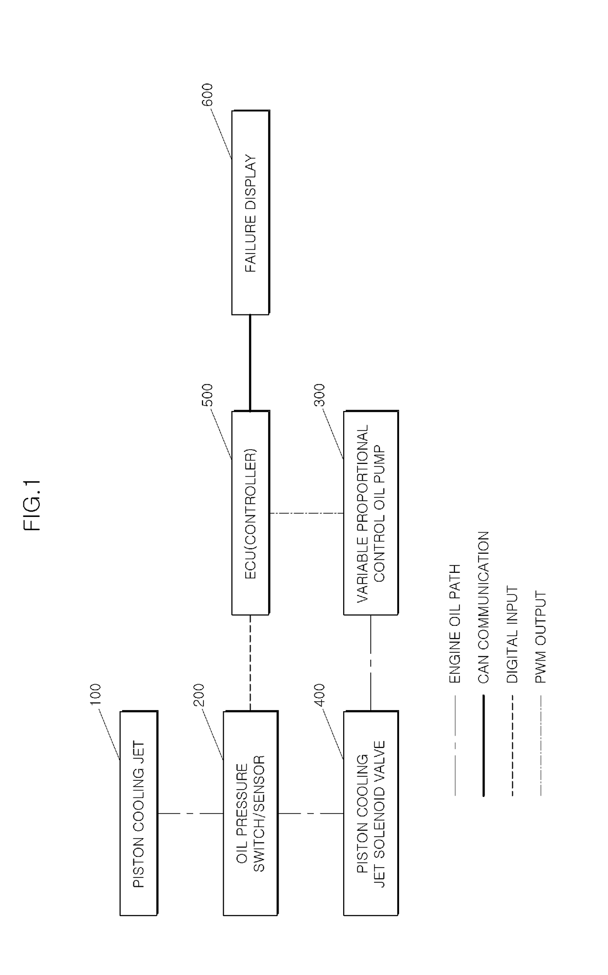
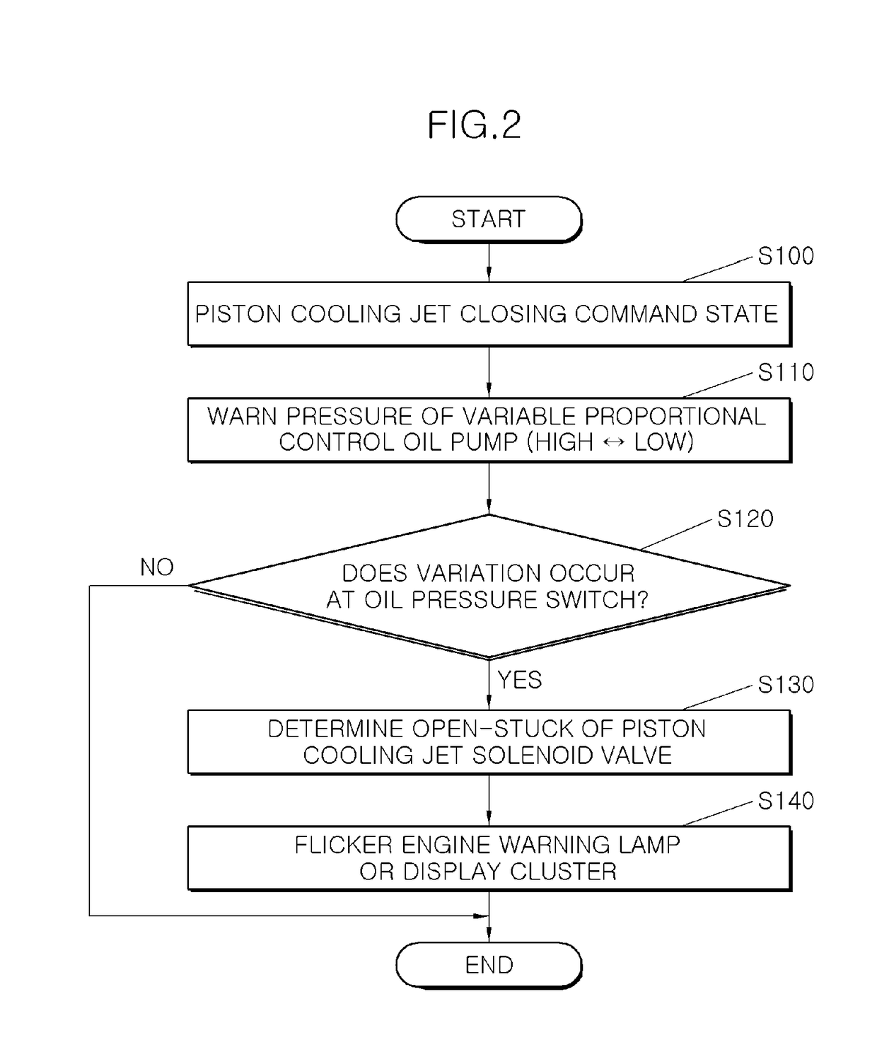
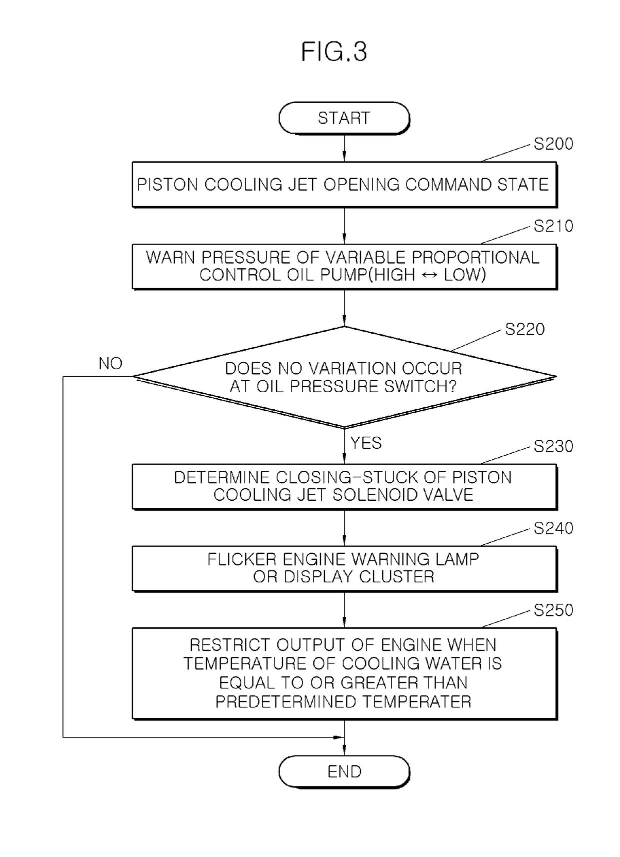
[0016]In accordance with the present disclosure, even after the engine is started, failure due to a stuck of the piston cooling device may be effectively determined according to a variation of an oil pressure using a variable proportional control oil pump that is used for fuel efficiency enhancement. Additionally, in accordance with the present disclosure, when an open-stuck or a closing-stuck occurs at a solenoid valve of the piston cooling device, the jam may be indicated using an engine warning lamp or a display device to prevent excessive emission of exhaust gas. Further, in accordance with the present disclosure, when a closing-stuck occurs at the solenoid valve of the piston cooling device, an engine output may be restricted when a temperature of the engine increases over a predetermined level or greater to prevent damage to the engine.

Problems solved by technology

However, such a conventional method for determining a solenoid valve failure is unable to be used after the engine is started due to a characteristic of the conventional method.
In particular, after the solenoid valve 26 of the piston cooling jet is opened for the first time, a pressure is formed in an oil flow path of the piston cooling jet irrespective of an opening or closing state of the piston cooling jet causing diagnosis to be difficult.
Consequently, the conventional method for determining a solenoid valve failure is used only when ignition is in an OFF state or in a key-on state, and, after the engine is started, that is, after a solenoid valve of the piston cooling jet is opened for the first time, failure determination becomes difficult, thus causing inaccurate diagnosis results.
Additionally, the method may further include, when the failure is determined to occur at the piston cooling device, restricting an output of an engine when a temperature of cooling water of the engine is equal to or greater than a preset temperature.

Method used


Image

  • Method and system for diagnosing failure of piston cooling device
  • Method and system for diagnosing failure of piston cooling device
  • Method and system for diagnosing failure of piston cooling device

Examples


Embodiment Construction

[0022]It is understood that the term “vehicle” or “vehicular” or other similar term as used herein is inclusive of motor vehicles in general such as passenger automobiles including sports utility vehicles (SUV), buses, trucks, various commercial vehicles, watercraft including a variety of boats and ships, aircraft, and the like, and includes hybrid vehicles, electric vehicles, combustion, plug-in hybrid electric vehicles, hydrogen-powered vehicles and other alternative fuel vehicles (e.g. fuels derived from resources other than petroleum).

[0023]Although exemplary embodiment is described as using a plurality of units to perform the exemplary process, it is understood that the exemplary processes may also be performed by one or plurality of modules. Additionally, it is understood that the term controller / control unit refers to a hardware device that includes a memory and a processor. The memory is configured to store the modules and the processor is specifically configured to execute ...


PUM


Abstract

A method for diagnosing a failure of a solenoid valve of a piston cooling device is provided. The method includes varying a pressure in a variable proportional control oil pump when an opening command or a closing command of the solenoid valve is sent to inject oil from the piston cooling device. Additionally, a variation of an oil pressure in an oil flow path of the piston cooling device is monitoring according to a variation of the pressure in the variable proportional control oil pump and whether a failure occurs at the solenoid valve of the piston cooling device is then determined.

Description

CROSS-REFERENCE TO RELATED APPLICATIONS[0001]This application claims priority to Korean Patent Application No. 10-2017-0115095, filed on Sep. 8, 2017, which is incorporated herein by reference in its entirety.BACKGROUNDField of the Invention[0002]The present disclosure relates to a method for diagnosing failure of a piston cooling device, and more particularly, to a diagnosis method and a diagnosis system, which are capable of diagnosing whether a failure occurs at a piston cooling jet when an engine is started.Description of Related Art[0003]A piston cooling device is a device configured to cool a piston exposed to a high temperature and a high pressure to maintain heat resistance and durability thereof. A piston cooling jet is known as a type of piston cooling device and injects oil of an oil pan into a piston of an engine to cool a piston exposed to a high temperature and a high pressure. Recently, as emission regulation is strengthened, a piston cooling jet solenoid valve system...

Claims


Application Information

Patent Timeline
Patent Type & Authority Applications(United States)
IPC IPC(8): F01P3/08F02F3/16F02D35/02
CPCF01P3/08F02F3/16F02D35/02F01P2031/20F02D41/221F02D2041/227F02D2200/021F02D2250/26F01M1/08F02D41/22F01M1/02F01M1/18F01M2001/0246Y02T10/40F01M1/20F01M11/12F02D2041/228
Inventor KIM, JIN-SUNGCHOI, KWANG-SEOK
Owner HYUNDAI MOTOR CO LTD
Why Eureka
Try Eureka