Hybrid brake-by-wire system using a motor-magnetostrictive actuator combination

a technology of motor magnetostrictive actuator and hybrid brake, which is applied in the direction of braking systems, mechanical equipment, transportation and packaging, etc., can solve the problems of increasing the brake distance and unguaranteed vehicle braking safety, reducing reliability, and increasing the energy consumption of the brake, so as to improve the safety of the vehicle braking system, the effect of increasing the vehicle mass and high power consumption

Active Publication Date: 2019-03-21
HEFEI UNIV OF TECH
View PDF0 Cites 14 Cited by
  • Summary
  • Abstract
  • Description
  • Claims
  • Application Information

AI Technical Summary

Benefits of technology

[0012]The present invention is to solve the existing technical problems, providing a hybrid brake-by-wire system using a motor-magnetostrictive actuator combination to simplify the braking system and greatly reduce the system quality, and finally improve the system performances, especially the braking safety.
[0013]The present invention discloses a hybrid brake-by-wire system using a motor-magnetostrictive actuator combination. The system includes a motor, a transmission mechanism, a magnetostrictive-driving piston mechanism and a floating-caliper disc mechanism, wherein the transmission mechanism including a planetary gear set and a screw set is driven by the motor. The linear motion of the sleeve is achieved by the planetary gear set and screw set. The piston head of the magnetostrictive-driving piston mechanism pushed forward by both the sleeve and the magnetostrictive rod drives the brake pad back plate to clamp the brake disc through the right and left brake pads of the floating-caliper disc mechanism, which accomplishes braking.

Problems solved by technology

The new brake-by-wire system try to avoid the congenital defects of the traditional hydraulic, pneumatic and electromagnetic braking system such as the complexity of the system, high energy consumption and relatively low response speed (which means longer braking distance), but the brake-by-wire system itself is still in pre-researching and explore stage.
However, there are inherent drawbacks of the conventional braking systems as follows:(a) The long and sophisticated pipelines / valves of hydraulic and / or pneumatic braking systems lead to slow braking pressure transfer and then braking delay, which results in the increase of brake distance and unguaranteed vehicle braking safety.(b) The complex pipelines and valves greatly increase complexity of the system and control, reduce reliability thereof, and thus the cost of braking system remains high.(c) The pipelines, valves or electromagnetic actuators greatly increase the weight of the systems.
Undoubtedly, the conventional hydraulic, pneumatic and electromagnetic braking systems are unbeneficial to achieve energy saving and emission reduction.
)(d) The hydraulic oil fulfilled in the hydraulic braking systems is flammable and may leak, which would possibly cause environment pollution and even threatens crash safety of automobiles.
However, it is presently at very start phase of investigation and industrial applications, and there are still some fatal problems of the existing BBW systems:(a) Majority of the existing BBW systems are using motors as the only actuator.
However, the driving power of the motor is limited because of quite limited installation space.
But the excessive speed reduction ratio may equal to long response time of driving mechanism based on the motor and ball-screw set.
Thus, the accuracy of the states of reducing the torque, holding the torque and increasing the torque of ABS cannot be guaranteed.
The braking distance increases and braking safety is threatened in turn.(c) What is more important, for the BBW systems using motors as the only actuator, the motor may be stalling during long-time braking and could lead to motor burnout, which would directly lead to the failure of braking systems.

Method used


Image

  • Hybrid brake-by-wire system using a motor-magnetostrictive actuator combination
  • Hybrid brake-by-wire system using a motor-magnetostrictive actuator combination
  • Hybrid brake-by-wire system using a motor-magnetostrictive actuator combination

Examples


Embodiment Construction

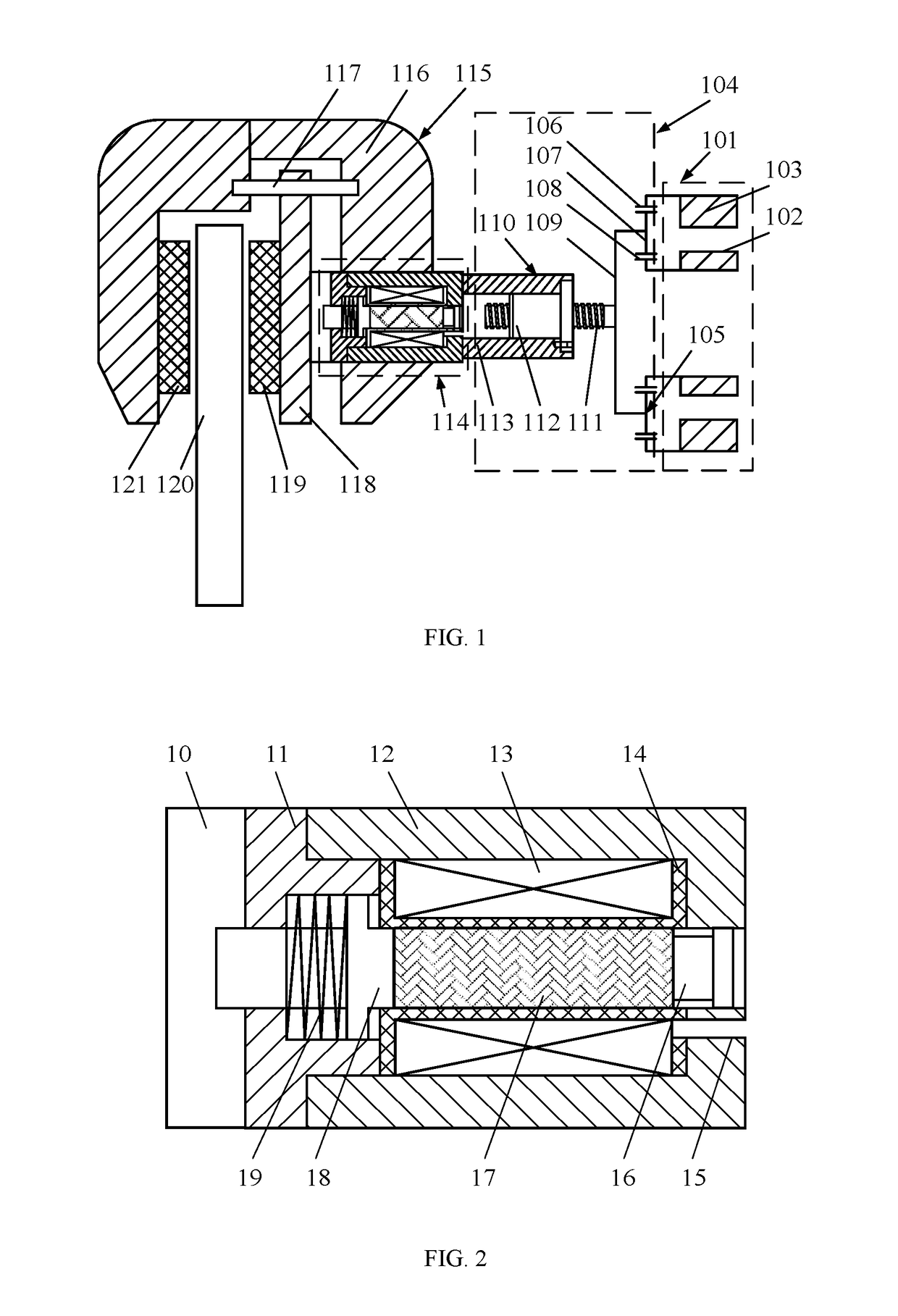
[0043]FIGS. 1 and 2 show a hybrid brake-by-wire system using a motor-magnetostrictive actuator combination, which in detail consists of a motor 101, transmission mechanism 104, magnetostrictive-driving piston mechanism 114 and floating-caliper disc mechanism 115 in the present embodiment.

[0044]FIG. 1 is a view showing that the motor 101 includes a stator 102 and a rotor 103, and the transmission mechanism 104 includes a planetary gear set 105 and a screw set 110. The planetary gear set 105 includes a ring gear 106, planet gears 107, a sun gear 108 and a carrier 109. The ring gear 106 is fixedly connected with the rotor 103 and driven by the motor 101, and the carrier 109 is coaxially assembled with the sun gear 108 and the screw 111. The screw 111 is assembled on the carrier 109 via a connecting key. The nut 112 and screw 111 are connected via threads. The rear end of the sleeve 113 is fixedly connected to the nut 112 through bolts and driven by the motor 101. The linear motion of t...


PUM


Abstract

The present invention discloses a motor-magnetostrictive actuator hybrid brake-by-wire system. The system includes a motor, a transmission mechanism, a magnetostrictive-driving piston mechanism and a floating-caliper disc mechanism. The transmission mechanism includes a planetary gear set and a screw set, and is driven by the motor. The linear motion of the sleeve is achieved by the planetary gear set and screw set. The sleeve pushes forward the piston head of the magnetostrictive-driving piston mechanism and the piston head pushes forward the brake pad back plate of the floating-caliper disc mechanism to clamp the brake disc, which accomplishes braking. The present invention uses the motor and the magnetostrictive-driving piston mechanism as a combined BBW system, which will simultaneously solve the problems of slow response, low precision and motor stalling effect of the only motor-driving braking systems and, also avoid the drawback of insufficient mechanical capabilities of the only magnetostrictive actuator-driving braking systems.

Description

TECHNICAL FIELD[0001]The present invention relates to a disc brake, and more particularly to a hybrid brake-by-wire system using a motor-magnetostrictive actuator combination.BACKGROUND OF THE INVENTION[0002]Automobiles, as one of the most important means of transportation vehicles, have developed, updated and innovated with dramatically fast development of science and technology. No matter how the automotive technology develops, vehicle's safety and energy saving have been always the core topics in the automotive industry and also the most concerned points of the customers. As one of the major automotive systems, the braking system plays a vital role in driving safety. At present, brake-by-wire system is rapidly developing as a new type of automobile braking system besides the traditional hydraulic, pneumatic and electromagnetic braking system. The new brake-by-wire system try to avoid the congenital defects of the traditional hydraulic, pneumatic and electromagnetic braking system...

Claims


Application Information

Patent Timeline
Patent Type & Authority Applications(United States)
IPC IPC(8): B60T13/74F16D55/226F16D65/18H02K7/116
CPCB60T13/741F16D55/226F16D65/18H02K7/116F16D2066/003F16D2066/005F16D2121/28F16D2125/587F16D2125/40F16D2125/50F16D2121/24F16D55/2265F16D2055/0091B60T13/667B60T13/748F16D65/183F16D2121/20F16D2125/36
Inventor BAI, XIANXULI, YANGCAI, FEILONGSI, ZHIYUANQIAN, LIJUN
Owner HEFEI UNIV OF TECH
Why Eureka
Try Eureka