

Method and apparatus for frame rate boosting in lidar array
- Summary
- Abstract
- Description
- Claims
- Application Information
AI Technical Summary
Benefits of technology
Problems solved by technology
Method used
Image

Examples
Embodiment Construction
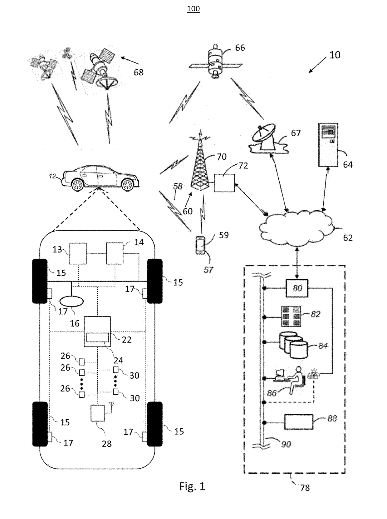
[0019]The following detailed description is merely exemplary in nature and is not intended to limit the disclosure or the application and uses thereof. Furthermore, there is no intention to be bound by any theory presented in the preceding background or the following detailed description. For example, the LiDAR sensor of the present invention has particular application for use on a vehicle. However, as will be appreciated by those skilled in the art, the LiDAR sensor of the invention may have other applications.
[0020]Modern vehicles sometimes include various active safety and control systems, such as collision avoidance systems, adaptive cruise control systems, lane keeping systems, lane centering systems, etc., where vehicle technology is moving towards semi-autonomous and fully autonomous driven vehicles. For example, collision avoidance systems are known in the art that provide automatic vehicle control, such as braking, if a potential or imminent collision with another vehicle o...
PUM
 Abstract
Description
Claims
Application Information