Cell culture device and cell culture method

Active Publication Date: 2019-03-28
NAT INST OF ADVANCED IND SCI & TECH
View PDF1 Cites 6 Cited by
  • Summary
  • Abstract
  • Description
  • Claims
  • Application Information

AI Technical Summary

Benefits of technology

[0044]According to an aspect of the present invention, it is possible to introduce the liquid from the space on the other surface side of the membrane into the second liquid storage chamber, and therefore, to simplify the structure of the flow path for liquid transfer. For this reason, it is possible to miniaturize the device by simplifyi

Problems solved by technology

As described in Non-Patent Documents 1 and 2, development cost for pharmaceutical products in recent years has increased exponentially, and the success rate of clinical trials has decreased year by year.
In addition, the cost for developing chemical products such as cosmetics has similarly increased.
As the reason for this, for example, due to the species difference between animals and humans, results of animal experiments cannot be directly extrapolated to clinical trials.
In addition, in the development of chemical products such as cosmetics, in some cases, it is difficult to use experimental animals, especially in Europe.
On the other hand, monolayer culture used in cell assays in the conventional art is often problematic in that the en

Method used


Image

  • Cell culture device and cell culture method
  • Cell culture device and cell culture method
  • Cell culture device and cell culture method

Examples


Example

[0068]A cell culture device 10 according to a first embodiment will be described with reference to the drawings.

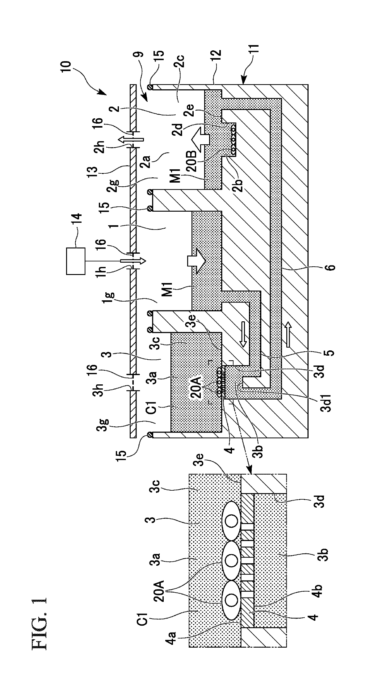
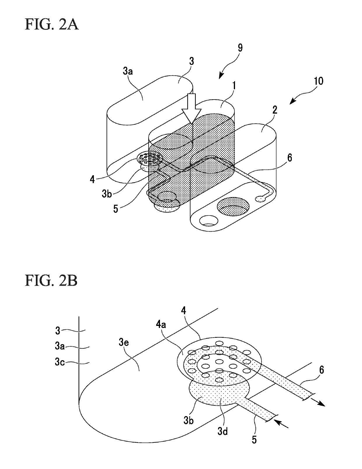
[0069]FIG. 1 is a cross-sectional view schematically showing the cell culture device 10. FIG. 2A is a perspective view schematically showing the cell culture device 10. FIG. 2B is an enlarged view showing a part of the cell culture device 10.

[0070]As shown in FIGS. 1, 2A, and 2B, the cell culture device 10 includes a storage tank 11 and a pressurizing pump 14. The storage tank 11 includes one cell culture unit 9. The storage tank 11 includes a container-shaped tank main body 12 and a lid portion 13.

[0071]The cell culture unit 9 has a first liquid storage chamber 1, a second liquid storage chamber 2, a culture liquid storage chamber 3, a membrane 4, a liquid introduction flow path 5, and a liquid lead-out flow path 6. The first liquid storage chamber 1 and the second liquid storage chamber 2 are spaces formed by recess portions formed on the upper surface of the tank main b...

Example

Second Embodiment

[Cell Culture Device]

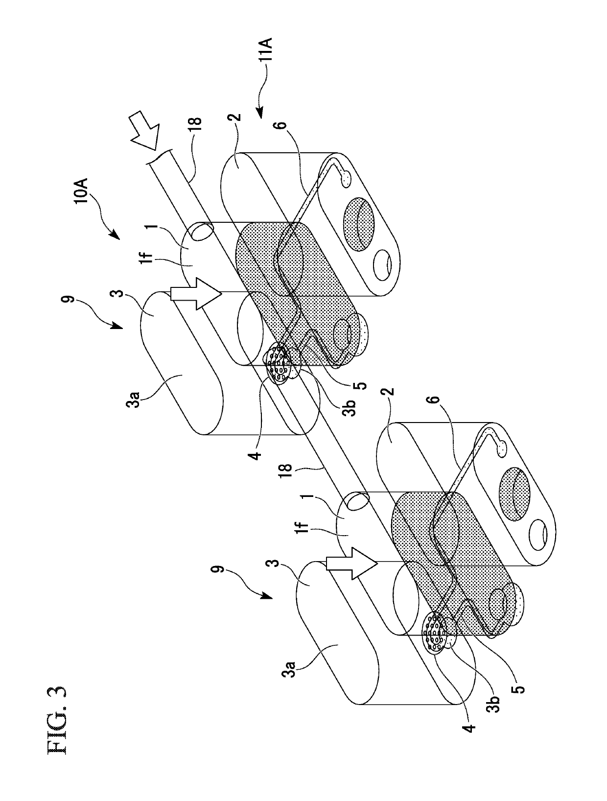
[0097]A cell culture device 10A according to a second embodiment will be described with reference to the drawings. Hereinafter, the same configurations as those described above are given the same reference numerals, and the description thereof will not be repeated.

[0098]As shown in FIG. 3, a storage tank 11A in the cell culture device 10A has a plurality of cell culture units 9. The number of cell culture units 9 may be any number of two or more.

[0099]Among the plurality of cell culture units 9, first liquid storage chambers 1 and 1 of two adjacent cell culture units 9 and 9 are connected with each other through a gas flow path 18. One end and the other end of the gas flow path 18 are connected to upper gas phase spaces if and if in the first liquid storage chambers 1 and 1, and therefore, the gas flow path 18 is connected to the first liquid storage chambers 1 and 1 so that gas is able to flow therethrough. In a case where the number of cell cu...

Example

Third Embodiment

[Cell Culture Device]

[0105]A cell culture device 10E according to a third embodiment will be described with reference to the drawings.

[0106]As shown in FIG. 4, a storage tank 11E of the cell culture device 10E includes a tank main body 12E and a lid portion 13E. The storage tank 11E includes a cell culture unit 9E. The cell culture unit 9E has a first liquid storage chamber 1E, a second liquid storage chamber 2E, a culture liquid storage chamber 3E, a membrane 4, a liquid lead-out flow path 6E, and a liquid return flow path 7.

[0107]The tank main body 12E includes a main portion 12E1 in which the first liquid storage chamber 1E and the second liquid storage chamber 2E are formed, and a culture liquid storage tank 3E1. The culture liquid storage chamber 3E is an internal space of the culture liquid storage tank 3E1.

[0108]The second liquid storage chamber 2E has a main chamber 2Ec and a cell-holding recess portion 2Ed (cell-holding portion) formed on a bottom surface 2E...


PUM


Abstract

A cell culture device includes a storage tank having one or a plurality of cell culture units. Each of the cell culture units includes a first liquid storage chamber having an airtight structure in which a liquid is to be stored, a second liquid storage chamber in which the liquid is to be stored, a culture liquid storage chamber having a culture liquid storage space in which a culture liquid of cells is to be stored, a permeable membrane having one surface to which the cells are able to adhere, said one face facing the culture liquid storage space, and a liquid lead-out flow path that introducing the liquid from a space on the other surface side of the membrane into the second liquid storage chamber, the first liquid storage chamber being set as a supply source of the liquid.

Description

TECHNICAL FIELD[0001]The present invention relates to a device that cultures cells and a method of culturing cells using the device.[0002]Priority is claimed on Japanese Patent Application No. 2016-45023, filed on Mar. 8, 2016, the content of which is incorporated herein by reference.BACKGROUND ART[0003]As described in Non-Patent Documents 1 and 2, development cost for pharmaceutical products in recent years has increased exponentially, and the success rate of clinical trials has decreased year by year. In addition, the cost for developing chemical products such as cosmetics has similarly increased. As the reason for this, for example, due to the species difference between animals and humans, results of animal experiments cannot be directly extrapolated to clinical trials. In addition, in the development of chemical products such as cosmetics, in some cases, it is difficult to use experimental animals, especially in Europe. Under such circumstances, there are increasing expectations...

Claims


Application Information

Patent Timeline
IPC IPC(8): C12M1/00C12M1/02C12M1/12
CPCC12M23/34C12M27/00C12M25/02C12M23/38C12M29/20
Inventor SUGIURA, SHINJISATOH, TAKUKANAMORI, TOSHIYUKISHIN, KAZUMI
Owner NAT INST OF ADVANCED IND SCI & TECH
Why Eureka
Try Eureka