Multi-resolution scan matching with exclusion zones

a scanning and exclusion zone technology, applied in the field of robot navigation, can solve the problems of repetitive and laborious delivery of orders to shipping stations, easy errors, and logistical challenges

Active Publication Date: 2019-03-28
LOCUS ROBOTICS CORP
View PDF0 Cites 68 Cited by
  • Summary
  • Abstract
  • Description
  • Claims
  • Application Information

AI Technical Summary

Benefits of technology

[0010]The benefits and advantages of the present invention over existing systems will be readily apparent from the Brief Summary of the Invention and Detailed Description to follow. One skilled in the art will appreciate that the present teachings can be practiced with embodiments other than those summarized or disclosed below.

Problems solved by technology

Fulfilling such orders in a timely, accurate and efficient manner is logistically challenging to say the least.
The process of receiving an order, planning its fulfillment, finding the storage shelf or bin, picking the product, and repeating the process for each item on the order, then delivering the order to a shipping station is repetitive and labor intensive.
However, SLAM is susceptible to pose errors due to uncertainties in robot obstacle sensing, robot control and location sensing, and the mapping process itself.
Conventional methods for preventing such errors are computationally expensive.

Method used


Image

  • Multi-resolution scan matching with exclusion zones
  • Multi-resolution scan matching with exclusion zones
  • Multi-resolution scan matching with exclusion zones

Examples


Embodiment Construction

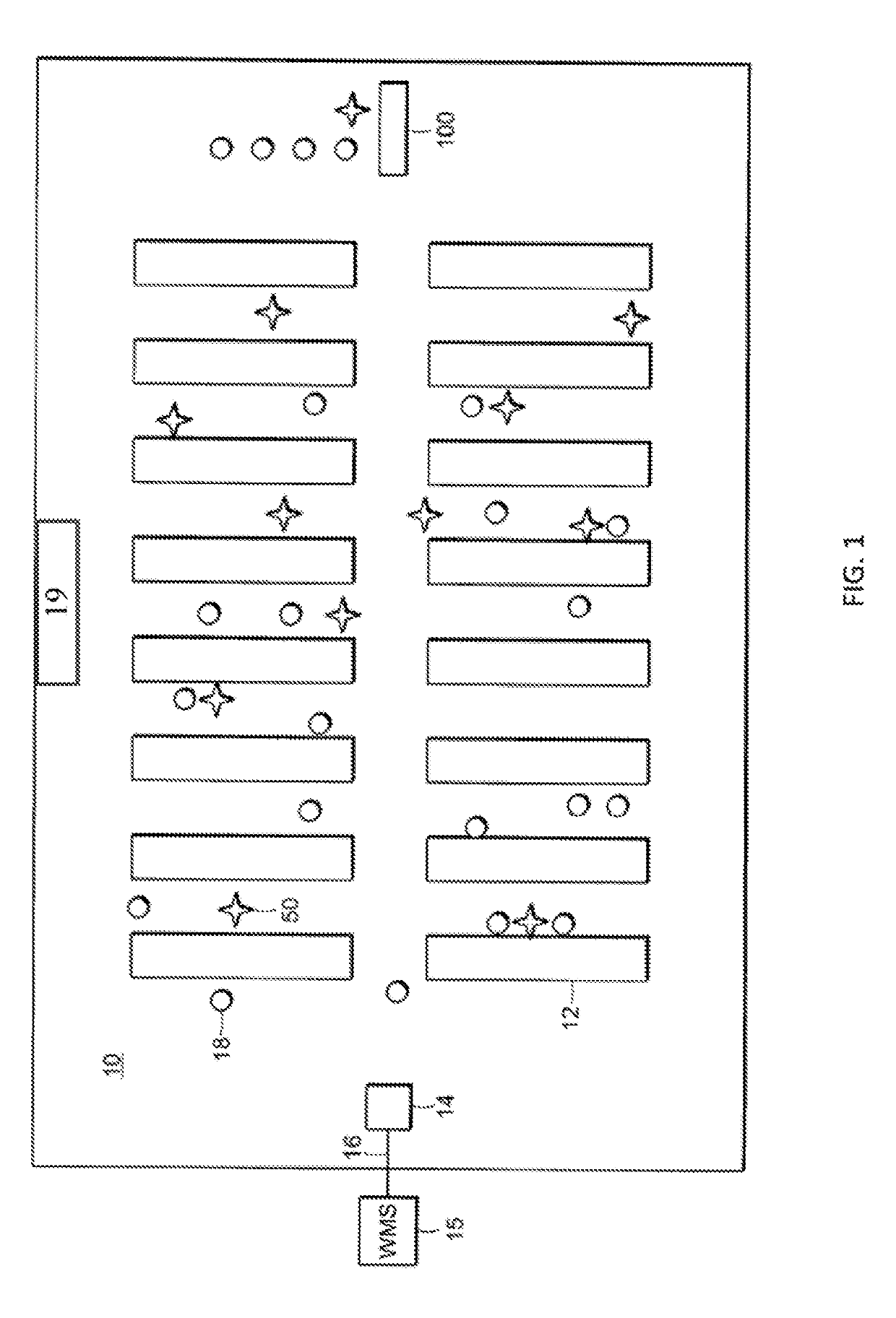
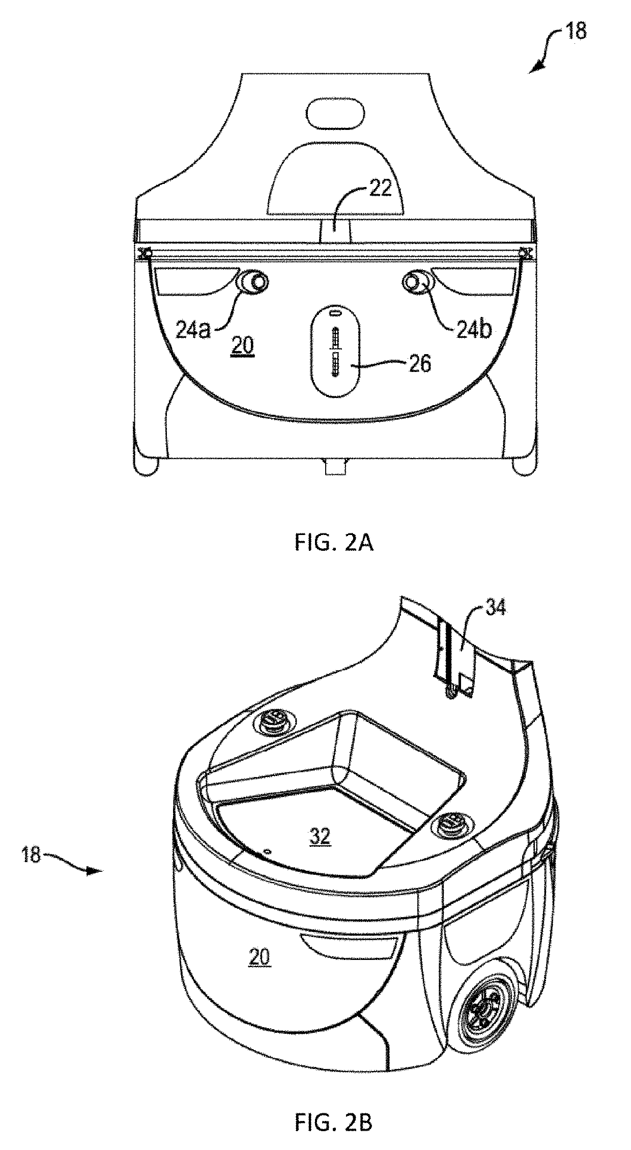
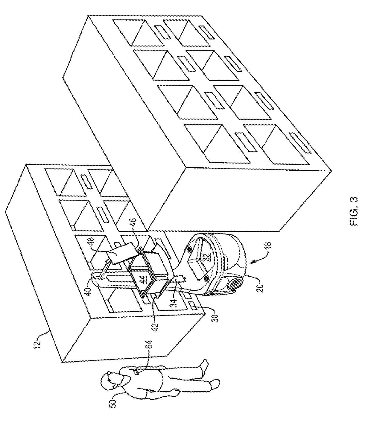
[0043]The invention described herein is directed to methods and systems for use with an autonomous or semi-autonomous robot for improved navigation of the robot from a current location to a target location along its “goal path”, within an environment containing obstacles and free space.

[0044]Specifically, the methods and systems of the present invention provide a computationally efficient improvement over the prior art for accurately determining the present position and orientation or “pose” of the robot within a spatial environment. Having determined its pose quickly and accurately, the robot may better control its movement along the goal path, avoiding obstacles and allowing the robot to more directly and more smoothly among obstacles in the environment. Furthermore, the reduced processing time required by the pose determination frees up computational resources for other tasks performed by the robot during an allotted processing cycle time.

[0045]The disclosure and the various feat...


PUM


Abstract

A method for navigating a robot from a current pose to a goal pose. A map represents obstacles and free space within an area for robot navigation. A matching map pyramid and an exclusion map pyramid are constructed based on the map and decimations from a highest resolution to successively lower resolutions of the map pyramids. Current pose for navigating from a current location to a goal pose along a goal path includes determining a search area and creating a search heap. Scoring of search tasks on the search heap determines a best candidate pose at a highest resolution matching map, or expands the search heap with search tasks at the next higher resolution matching map. Expanding the search heap at the next higher resolution matching map avoids search tasks that would localize the robot in an exclusion zone.

Description

CROSS-REFERENCE TO RELATED APPLICATIONS[0001]This application is related to U.S. application Ser. No. 15 / 712,256 filed Sep. 22, 2017, entitled “DYNAMIC WINDOW APPROACH USING OPTIMAL RECIPROCAL COLLISON AVOIDANCE COST-CRITIC”, which is incorporated herein by reference.FIELD OF THE INVENTION[0002]The invention described herein relates generally to the navigation of robots to target locations using spatial representations of a dimensional space containing obstacles. Specifically, the present invention is an improved method of determining the pose of an autonomous or semi-autonomous robot operating an order fulfillment warehouse to fulfill or assist at the fulfillment of product orders.BACKGROUND OF THE INVENTION[0003]In many applications, robots are used to perform functions in place of humans or to assist humans in order to increase productivity and efficiency. One such application is order fulfillment, which is typically performed in a large warehouse filled with products to be shipp...

Claims


Application Information

Patent Timeline
Patent Type & Authority Applications(United States)
IPC IPC(8): G05D1/02B65G1/137B65G1/04
CPCG05D1/0248G05D1/0257G05D1/024B65G1/1373B65G1/0492G05D2201/0216B25J9/1666G05D1/0274G01C21/206
Inventor MOORE, THOMASPOWERS, BRADLEY
Owner LOCUS ROBOTICS CORP
Why Eureka
Try Eureka