
Eureka
For R&D, Eureka makes reading and utilizing patents & technical documents easy.
Eureka AIR
Designed for self-driven R&D workflows. Generate viable solutions, solve complex R&D challenges, empower your innovation with AI.

Eureka Materials
Designed for material experts only. Revolutionize your material R&D, from search, analyze, to developing new materials.

TechResearch
Generate reliable direction feasibility study reports for your R&D in just a few steps.

TechSeek
Discover and master advanced knowledge NOW. Basics, ideas, possibilities, all at once.

TechMind
As an expert in R&D Theories, TechMind can generates customized viable solutions instantly.

TechRisk
Analyze your overall solution with one click, know your potential R&D risks in advance.

TechMonitor
Get weekly tech updates, stay abreast of the latest tech innovations and key insights.
Package sealing structure, device package, and package sealing method
- Summary
- Abstract
- Description
- Claims
- Application Information
AI Technical Summary
Benefits of technology
Problems solved by technology
Method used
Image

Examples
first embodiment
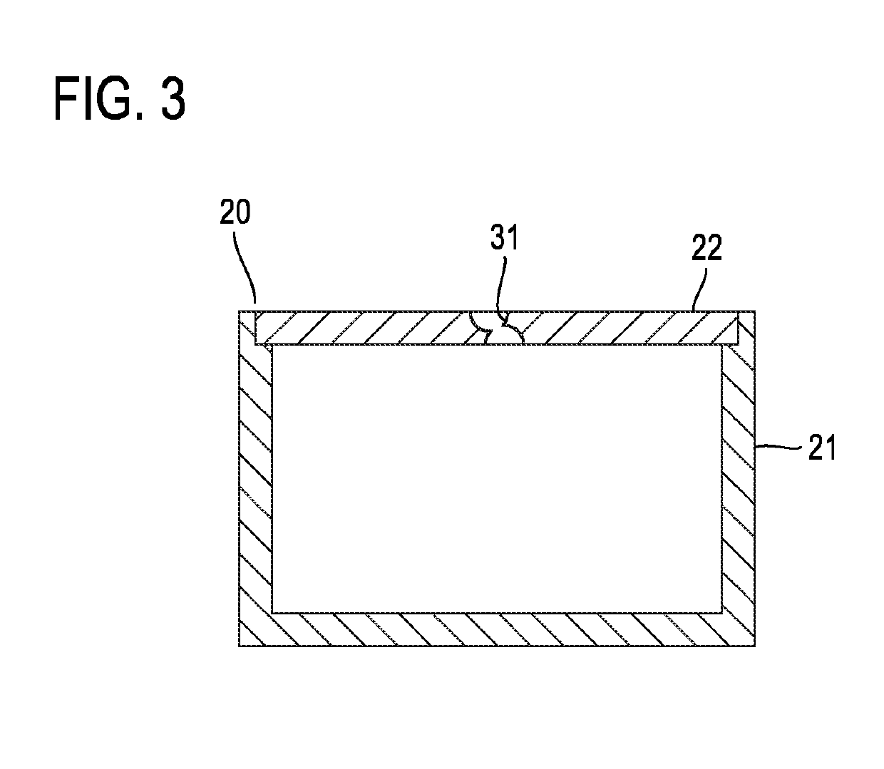
[0031]FIG. 3 illustrates an overview of a configuration of a package 20 for an acceleration sensor as an example of a device package. Components enclosed in the package 20 are omitted from FIG. 3.
[0032]The package 20 comprises a cylindrical housing 21 with a bottom, which has an opening at an opposite end of the bottom, and a cover 22 which covers the opening of the housing 21. Each of the housing 21 and the cover 22 is made of metal, for example stainless steel. The housing 21 and the cover 22 are joined together by laser welding.
[0033]A through-hole 31 to be used for hermetically sealing the package 20 is formed in the center of the cover 22. The through-hole 31 before the hermetic sealing is illustrated in FIG. 3.
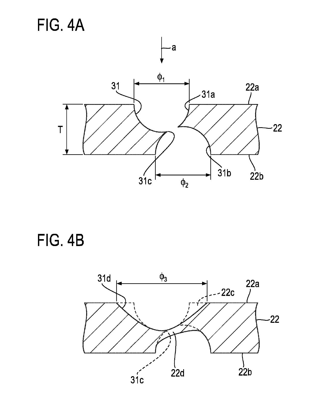
[0034]FIG. 4A illustrates the through-hole 31 in detail as a first example. The through-hole 31 is formed by simultaneously wet-etching both sides of the cover 22, namely the outer side 22a and the inner side 22b. When the cover 22 is viewed from directly above (i.e. whe...
second embodiment
[0042]FIG. 5A illustrates a through-hole 32 as a second example. The through-hole 32 is formed by drilling or by laser processing in which the inner side 22b of a cover 22 is irradiated with a laser beam.
[0043]The through-hole 32 has a tapered shape. The opening diameter ϕ5 of the through-hole 32 on the outer side 22a is smaller than the opening diameter ϕ4 of the through-hole 32 on the inner side 22b. The opening of the through-hole 32 on the outer side 22a represents a narrow neck. The opening diameters ϕ4 and ϕ5 are as follows, for example:
[0044]ϕ4=0.3 mm, ϕ5=0.15 mm
[0045]The outer opening periphery of the through-hole 32 is melted by irradiation of a laser beam in the direction indicated by arrow “a”. The outer opening periphery of the through-hole 32 is the region 22c represented by dashed lines in FIG. 5B. The melted outer opening periphery (i.e. melt) moves into the through-hole 32. A middle portion of the through-hole 32 is closed with the moved melt 22d as illustrated in FI...
third embodiment
[0049]A through-hole 33 is formed by simultaneously wet-etching the outer side 22a and the inner side 22b (FIG. 6). When the cover 22 is viewed from directly above, the location of the wet-etching on the outer side 22a coincides with the location of the wet-etching on the inner side 22b. Pits 33a, 33b are formed by the two-way wet-etching. When the pit 33a and the pit 33b connect to each other, the etching is stopped. As a result, a through-hole 33 in which the pit 33a and the pit 33b connect to each other through a narrow neck 33c in the thickness direction of the cover 22 is formed in the cover 22 as illustrated in FIG. 6.
PUM
 Abstract
Description
Claims
Application Information
 - R&D Engineer
- R&D Manager
- IP Professional
- Industry Leading Data Capabilities
- Powerful AI technology
- Patent DNA Extraction
Browse by: Latest US Patents, China's latest patents, Technical Efficacy Thesaurus, Application Domain, Technology Topic, Popular Technical Reports.
© 2024 PatSnap. All rights reserved.Legal|Privacy policy|Modern Slavery Act Transparency Statement|Sitemap|About US| Contact US: help@patsnap.com