

Thermowell With Expansion Joint
a technology of expansion joint and thermowell, which is applied in the direction of measurement devices, heat measurement, instruments, etc., can solve the problems of thermocouple failure, thermocouple failure, and no longer provide reliable temperature measuremen
- Summary
- Abstract
- Description
- Claims
- Application Information
AI Technical Summary
Benefits of technology
Problems solved by technology
Method used
Image

Examples
embodiment 70
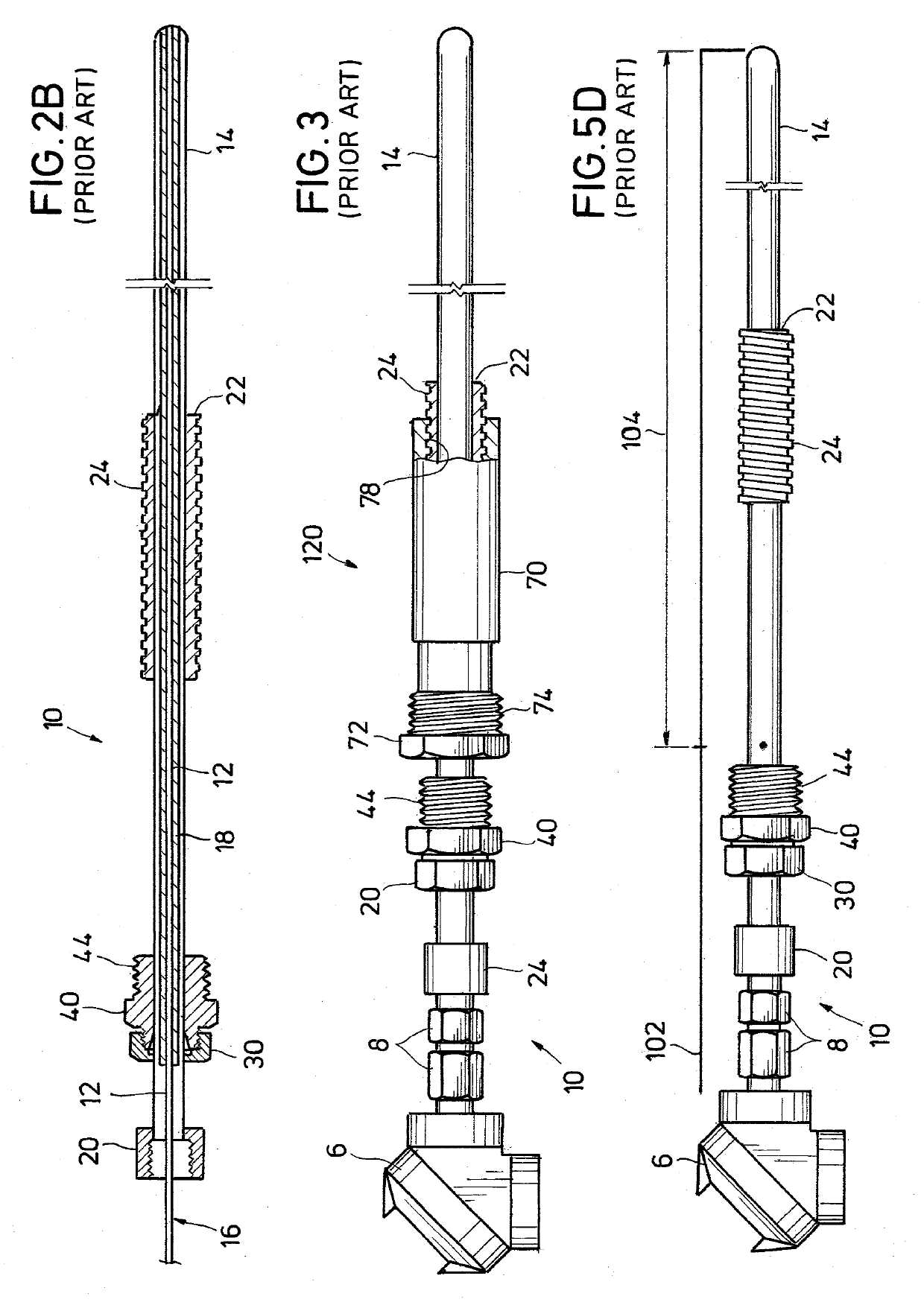
[0061]FIG. 3 shows an alternative embodiment 70 of a one-piece hollow fitting that is inserted through the mounting flange aperture 54 and coupled to the mounting flange 50. Fitting 70 is a bored-through, 1 inch diameter tube by 1.5 inch diameter pipe connector with male threads 74, which are threaded into the internal female threads 46 of the mounting flange 50. In addition to threads, the one-piece hollow fitting 70 may also be coupled to the mounting flange 50 using welding, press fitting, or other means. At its external or proximal end 72, fitting 70 has internal female threads 76, which are arranged to receive the male threads 44 of compression fitting 40. The fitting 70 also has internal female threads 78 with a left-hand thread pattern (for example), which is arranged and designed so that one counterclockwise or clockwise rotation of the thermowell tube 14 of the thermocouple-thermowell assembly 10 moves the assembly 10 a distance of 0.25 inch (for example) into or out of the...
embodiment 80
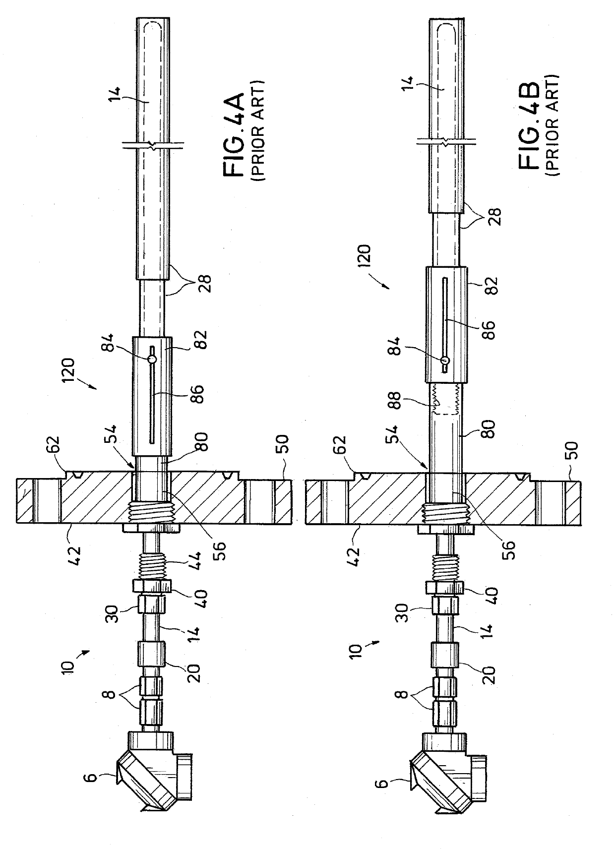
[0064]An advantage of the alternative embodiment 80 is the protection of outer surface ceramics 28 during the installation of the thermocouple-thermowell assembly 10. In process units with a refractory lining, the refractory 94 (see FIG. 5E) is typically rough and nonuniform, thereby causing the thermocouple-thermowell assembly 10 to contact the sides of the refractory 94 during installation. However, when using fitting 80, the outer protective sheath 82 and the attached ceramics / metal sleeves 28 only move longitudinally into and out of the interior 100 of the process unit or machine 90 even though the thermocouple-thermowell assembly 10 is being rotated through fitting 80 to adjust its depth. As a result, the alternative embodiment 80 greatly reduces the risk that a critical ceramic sleeve or tube 28 on the outer surface of the thermowell tube 14 that is attached to the sliding outer protective sheath 82 will be damaged by the refractory 94 during assembly 10 installation.
[0065]FIG...
embodiment 1
[0112]2. The assembly of embodiment 1, wherein the expansion joint comprises a bellows or a slip joint.
[0113]3. The assembly of embodiment 1, wherein the expansion joint comprises a slip joint, and wherein the slip joint has a noncircular cross-section, preferably a hexagonal cross-section.
[0114]4. The assembly of embodiment 1, wherein the expansion joint comprises a slip joint, wherein the thermowell tube comprises first and second portions, wherein the second portion slips over the first portion for providing the slip joint, wherein one of the first and second portions has a longitudinal slot and the other portion has a pin received in the slot, and wherein the slot and pin are sized and designed to provide desired limits for expansion and contraction, rotation and bending of the thermowell tube.
[0115]5. The assembly of embodiment 1, wherein the thermowell tube comprises a bellows.
[0116]6. The assembly of embodiment 1, wherein the thermowell tube comprises first and second portion...
PUM
| Property | Measurement | Unit |
|---|---|---|
| diameter | aaaaa | aaaaa |
| diameter | aaaaa | aaaaa |
| length | aaaaa | aaaaa |
Abstract
Description
Claims
Application Information