Leaning vehicle

a leaning vehicle and steering wheel technology, applied in the direction of rider propulsion, snowmobiles, bicycle equipment, etc., can solve the problems of motorcycle/scooter accidents, vehicle weight balancing, and thus even more noticeable weight balancing problems

Active Publication Date: 2019-04-11
BRUDELI TECH HLDG
View PDF21 Cites 10 Cited by
  • Summary
  • Abstract
  • Description
  • Claims
  • Application Information

AI Technical Summary

Benefits of technology

[0019]Further, by having the front suspension assembly connected to both the leaning frame and the suspension connecting element, the latter via the at least one shock absorber, the undercarriage element is kept in balance by the two front ground engaging members and prevented from tilting in a sideways direction. In other words, the front suspension assembly is connected to the leaning frame and the suspension connecting element, the latter via the at least one shock absorber, such that the undercarriage element is kept in balance by the two front ground engaging members.

Problems solved by technology

The latter is a common cause of motorcycle / scooter accidents.
Balancing the weight of vehicles during low speed maneuvering, especially those with a high Centre of Gravity (CoG), is a known problem for leaning vehicles having 3 or 4 wheels.
Leaning vehicle with 3 or 4 wheels will typically have a higher total mass than a comparable 2-wheeler (motorcycles / scooters), and the problem of weight balancing is thus even more noticeable.
A major problem with such extensive additions is an even higher CoG, and consequently, an increased problem of balancing the weight of the vehicle.
A further issue with leaning vehicles, is that the presence of three or four rotating wheels, as opposed to two in a common motorcycle, provides an increased resistance towards change of the tilt angle of the vehicle due to the increased total moment of inertia.
However, the force needed to balance the total weight is quite high and the use of footboards is not an ideal solution for most people.

Method used


Image

  • Leaning vehicle
  • Leaning vehicle
  • Leaning vehicle

Examples


first embodiment

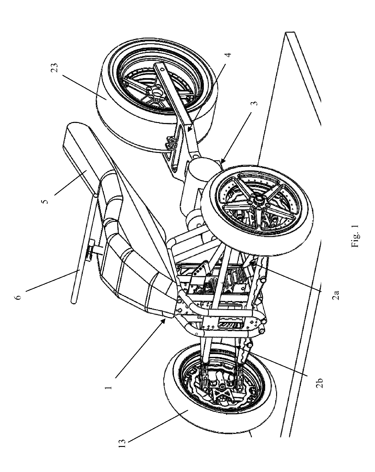
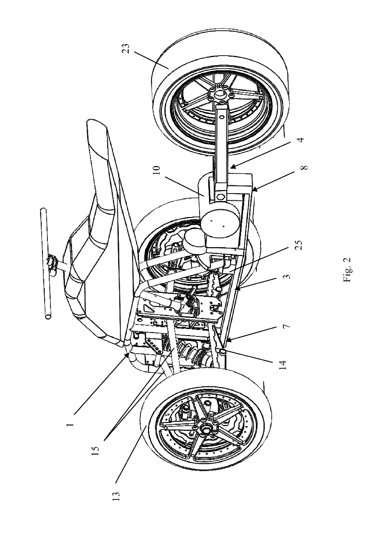
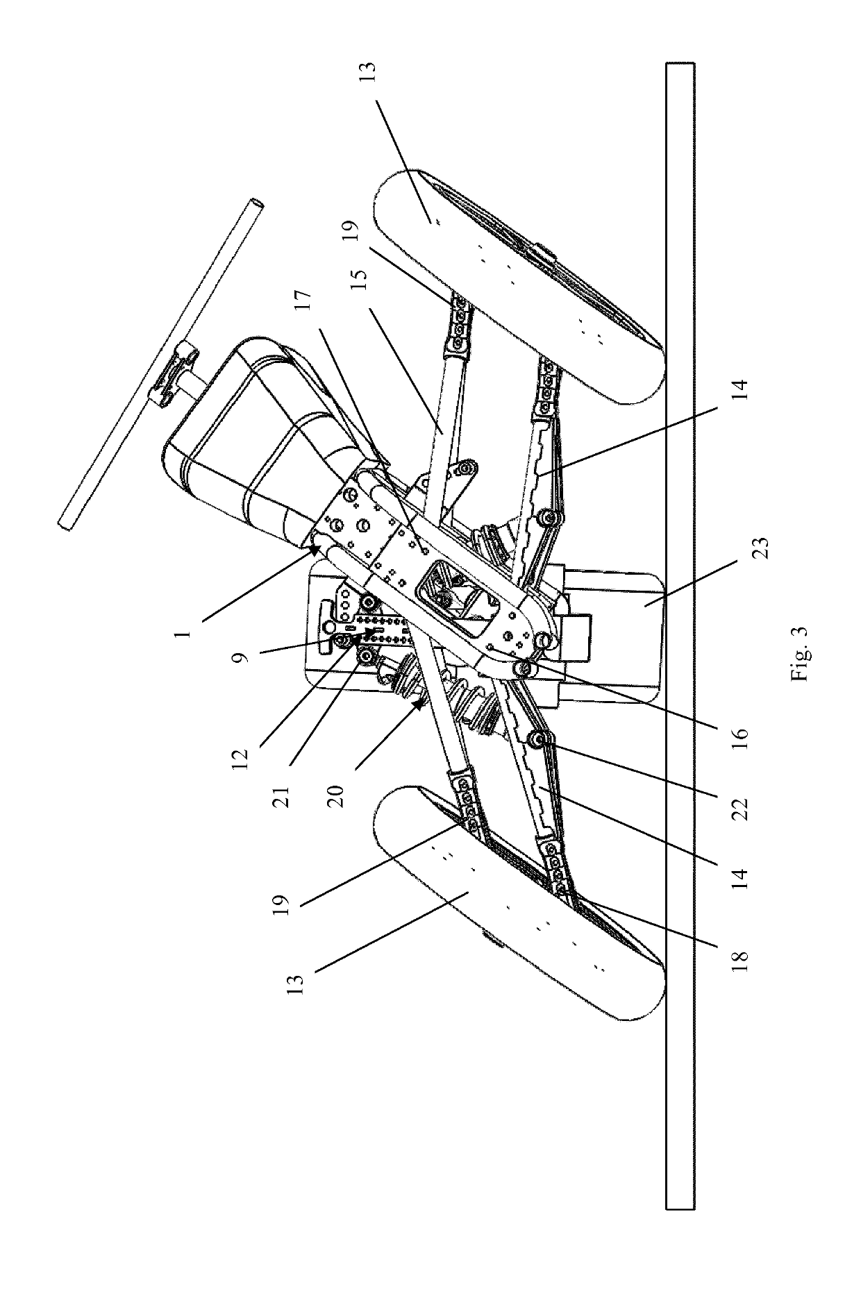
[0078]a leaning vehicle according to the invention is shown in FIGS. 1-5. The leaning vehicle, see FIGS. 1 and 2, comprises a leaning frame 1 having a handlebar 6 (i.e. a hand steering element) and a straddle seat 5. The leaning frame is operationally connected to a front left suspension assembly 2a and a front right suspension assembly 2b (or simply a front suspension assembly 2). Each of the front left suspension assembly 2a and the front right suspension assembly 2b comprises a lower suspension arm 14, an upper suspension arm 15 and a wheel (i.e. a ground engaging member), and are arranged such that both wheels will tilt in the same direction as the leaning frame when said frame pivots or tilts in a sideways direction. The leaning frame is further pivotally connected to an undercarriage element 3 by two pivot couplings 25, 26 (see also FIG. 5). The undercarriage element 3 is connected to a rear suspension assembly 4 comprising a rear wheel (i.e. a rear ground engaging element), s...

fourth embodiment

[0102]Apart from the design of the suspension connecting element, the features and function of the leaning vehicle of the fourth embodiment are the same as described for the embodiments disclosed above. In particular, the undercarriage element 3 is pivotally connected to the leaning frame, and connected to the rear suspension assembly 4 comprising a rear wheel, such that the leaning frame, and consequently the two front wheels 13, may move in a sideways direction independent of the undercarriage element and the rear wheel, i.e. the two front wheels and the leaning frame may tilt in a sideways direction without tilting the rear wheel (except the slight camber obtained due to the connection to the undercarriage element).

[0103]A fifth embodiment of the invention is illustrated in FIGS. 17-20. In the fifth embodiment, the front suspension assembly comprises two pull shock absorbers 52, each having an upper end connected to a respective upper suspension arm. The lower end of each shock a...

fifth embodiment

[0104]Apart from the design of the suspension connecting element, the features and function of the leaning vehicle of the fifth embodiment are the same as described for the embodiments disclosed above. In particular, the undercarriage element 3 and the front suspension assembly is pivotally connected to the leaning frame 1, and the undercarriage element connected to the rear suspension assembly 4 comprising a rear wheel 23, such that the leaning frame, and consequently the two front wheels 13 of the front suspension assembly, may move in a sideways direction independent of the undercarriage element and the rear wheel, i.e. the two front wheels and the leaning frame may tilt in a sideways direction without tilting the rear wheel.

[0105]Further, due to the connection between the undercarriage element and the shock absorbers of the front suspension assembly, via the shock connecting beam, the undercarriage element is stabilized by the two front wheels and prevented from tilting.


PUM


Abstract

The present invention provides a leaning vehicle comprising a leaning frame (1), a front suspension assembly (2), an undercarriage element (3), a rear suspension assembly (4) and a motor (10), wherein the leaning frame (1) comprises a straddle seat (5) and a hand steering element (6), the hand steering element operatively connected to the front suspension assembly (2); the undercarriage element comprises a front section (7) and a rear section (8), and is connected to a suspension connecting element (9); the front suspension assembly (2) comprises two ground engaging members (13) and at least one shock absorber (20), and is connected to the leaning frame (1) and the suspension connecting element, such that the ground engaging members (13) of the front suspension assembly will tilt in the same direction as the leaning frame; the rear suspension assembly (4) comprises at least one rear ground engaging member (23) and is connected to the rear section (8) of the undercarriage element; wherein the leaning frame (1) is pivotally connected to the undercarriage element (3), such that the leaning frame and the two ground engaging members may tilt in a sideways direction relative to the undercarriage element, the rear ground engaging member and the rear suspension assembly.

Description

FIELD OF THE INVENTION[0001]The present invention relates to the field of leaning vehicles, and in particular to motorized leaning vehicles.BACKGROUND[0002]Leaning vehicles (also known as tilting vehicles) having 3 or 4 wheels are well known. A common feature of such vehicles is the presence of two front wheels connected such that both front wheels lean in the same direction when the leaning vehicle is tilted in a sideways direction. Leaning vehicles have a number of advantages in that two front wheels increase the braking efficiency, i.e. reduced stopping length, and further in that the risk of front wheel slip is substantially reduced. The latter is a common cause of motorcycle / scooter accidents.[0003]Balancing the weight of vehicles during low speed maneuvering, especially those with a high Centre of Gravity (CoG), is a known problem for leaning vehicles having 3 or 4 wheels. Leaning vehicle with 3 or 4 wheels will typically have a higher total mass than a comparable 2-wheeler (m...

Claims


Application Information

Patent Timeline
Patent Type & Authority Applications(United States)
IPC IPC(8): B62K25/04B62K5/05B62K5/027B62K5/08B62K5/10B62K5/06
CPCB62K25/04B62K5/05B62K5/027B62K5/08B62K5/10B62K5/06B62K2005/001B62K25/28B62K5/01B62M27/02B62M2027/025B62K2204/00B62D9/02B60G21/007B60G2300/122B60G2300/322B60G2300/45
Inventor BRUDELI, GEIR
Owner BRUDELI TECH HLDG
Why Eureka
Try Eureka