
Electrically-conducting plate, uninterruptible sliding mechanism, and related server apparatus

a technology of electric conductivity and sliding mechanism, which is applied in the direction of casings/cabinets/drawers, casings/cabinets/drawers details, and support structure mounting, etc., can solve the problem that the server apparatus cannot be operated during the repair period, and achieve the effect of reducing the deformation stress applied to the elastic unit, avoiding instability, and increasing the whole resilience of the elastic uni

Active Publication Date: 2019-04-11
WIWYNN CORP
View PDF1 Cites 0 Cited by
  • Summary
  • Abstract
  • Description
  • Claims
  • Application Information

AI Technical Summary

Benefits of technology

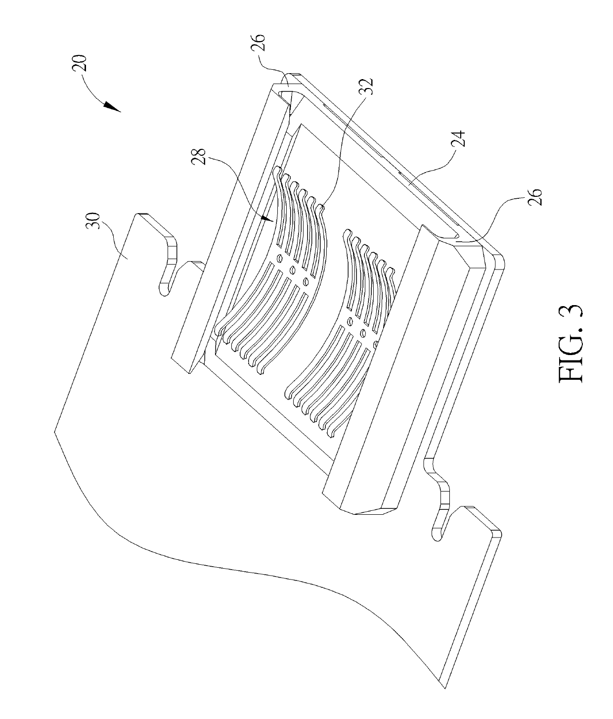
The present invention provides an electrically-conducting plate with an elastic piece set that can maintain its resilient property even under impact or assembly error. The elastic unit is designed as the arc structure, which can evenly distribute stress and reduce friction, resulting in stable voltage supply and reduced abrasion and scratch. The arc elastic unit has a large scale compression stroke and low stress concentration on the root portion, and can provide a preferred resilient recovering function in long term usage. The electrically-conducting plate can provide stable energy supply to the server unit, ensuring stable operation.

Problems solved by technology

While a conventional server apparatus is repaired, power supply of a server unit has to be cut off and then the server unit is removed from a rack for replacing electronic components, and the server apparatus cannot be operated during the repair period.
Accordingly design of a sliding mechanism capable of keeping the server unit stayed in an electrically-conducting state while being slid relative to the rack is an important issue in the related server industry.

Method used


Image

  • Electrically-conducting plate, uninterruptible sliding mechanism, and related server apparatus
  • Electrically-conducting plate, uninterruptible sliding mechanism, and related server apparatus
  • Electrically-conducting plate, uninterruptible sliding mechanism, and related server apparatus

Examples


Embodiment Construction

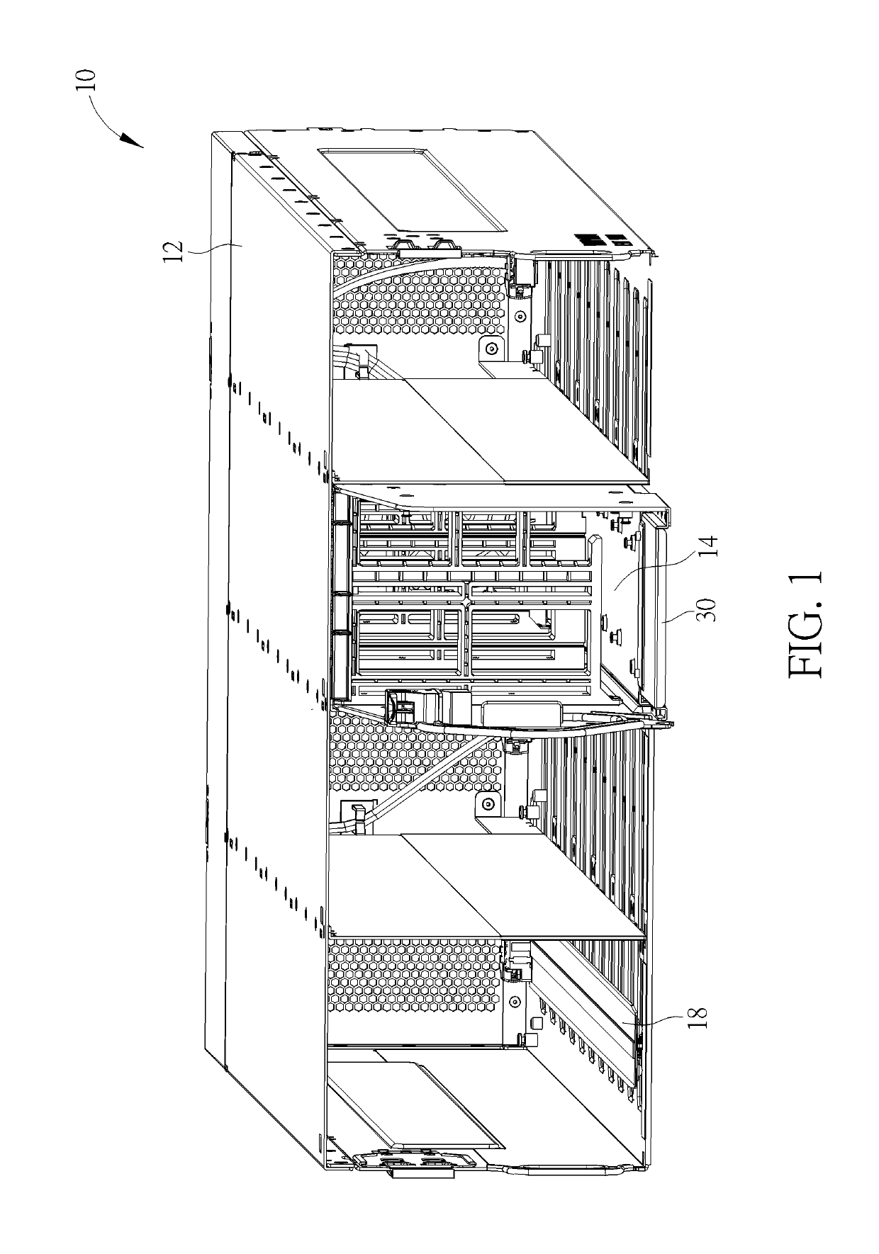
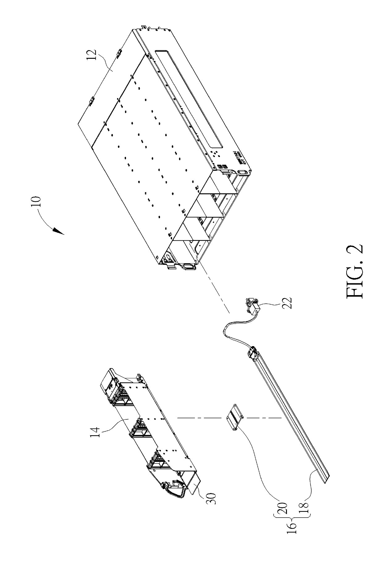
[0014]Please refer to FIG. 1 and FIG. 2. FIG. 1 is an assembly diagram of a server apparatus 10 according to an embodiment of the present invention. FIG. 2 is an exploded diagram of the server apparatus 10 according to the embodiment of the present invention. The server apparatus 10 includes a casing 12, a server unit 14 and an uninterruptible sliding mechanism 16. The server unit 14 can be disposed inside the casing 12 via the uninterruptible sliding mechanism 16, and be kept in an electrically-conducting state by the uninterruptible sliding mechanism 16 while the server unit 14 is slidably moved relative to the casing 12. For example, the uninterruptible sliding mechanism 16 has an electrically-conducting plate 20 slidably assembled with a discharging track 18 in a line contacting manner or in a surface contacting manner. The discharging track 18 is disposed inside the casing 12 and electrically connected with an external power supply 22 to acquire energy. The electrically-conduct...


PUM


Abstract

A server apparatus has a server unit disposed inside a casing via an uninterruptible sliding mechanism. The uninterruptible sliding mechanism includes a discharging track disposed on the casing and an electrically-conducting plate disposed on the server unit. The electrically-conducting plate is slidably assembled with the discharging track. The electrically-conducting plate includes abase, a buckling portion and an elastic piece set. The base is electrically connected to the server unit. The buckling portion is disposed on the base to engage with the discharging track. The elastic piece set is disposed on middle of the base and has at least one elastic unit. The elastic unit is an arc structure. An end of the arc structure is fixed to the base, and the other end of the arc structure abuts against the discharging track to continuously transmit energy output from the discharging track to the server unit via the base.

Description

BACKGROUND OF THE INVENTION1. Field of the Invention[0001]The present invention relates to a server apparatus capable of keeping an electrically-conducting state in assembly / disassembly process, and more particularly, to a server apparatus capable of utilizing an electrically-conducting plate and an uninterruptible sliding mechanism to keep the electrically-conducting state in assembly / disassembly process.2. Description of the Prior Art[0002]While a conventional server apparatus is repaired, power supply of a server unit has to be cut off and then the server unit is removed from a rack for replacing electronic components, and the server apparatus cannot be operated during the repair period. For improvement on a drawback of the conventional server apparatus, a flexible cable is set between the server unit and the rack, and two ends of the cable are respectively connected to the server unit and the power supply to accommodate the cable into a gap behind the server unit, so that the ca...

Claims


Application Information

Patent Timeline
Patent Type & Authority Applications(United States)
IPC IPC(8): H05K7/14H05K5/02H05K7/18
CPCH05K7/1417H05K5/0256H05K7/1491H05K7/183H05K7/1492
Inventor KAO, CHENG-SEN
Owner WIWYNN CORP
Learn More