
Apparatus for microwave hyperthermia

a hyperthermia and apparatus technology, applied in the field of microwave hyperthermia devices, can solve the problems of inconvenient use, user pain, and the thermotherapy device may be in a complex structure for the user, and achieve the effect of reducing or treating pain or inflammation

Active Publication Date: 2019-04-18
ELECTRONICS & TELECOMM RES INST
View PDF0 Cites 4 Cited by
  • Summary
  • Abstract
  • Description
  • Claims
  • Application Information

AI Technical Summary

Benefits of technology

The patent describes a device that uses microwaves to treat pain and inflammation in deep parts of the body, like joints and muscles. The device is easy to use and has a surface cover to prevent the microwaves from leaking or reflecting them towards the skin. The device can provide warm heat uniformly across a wide area, making it effective for treating pain and inflammation.

Problems solved by technology

Also, the thermotherapy device may be inconvenient for the user to easily carry and use, and may cause pain of the user, for example, a patient.
Since emitting of microwaves, monitoring of temperature, and cooling need to be performed at the same time, the thermotherapy device may be in a complex structure for the user to directly use.
Here, mismatching of microwaves may occur between the patch and the skin on which the patch is attached.
Damage, for example, burn may occur on the skin due to heat caused by the mismatching.
However, if the heat is cooled, the treatment effect of the thermotherapy device may be degraded.
In this case, the thermotherapy device may not generate heat that is uniformly distributed over the wide-range area from the body tissue of, for example, a joint, muscle, etc., of a leg, an arm, etc.
Also, the thermotherapy device needs to bi-directionally compress a target to be treated using a compression plate used to smoothly perform radio wave transmission of a waveguide antenna, which may cause inconveniences for a user, for example, a patient.

Method used


Image

  • Apparatus for microwave hyperthermia
  • Apparatus for microwave hyperthermia
  • Apparatus for microwave hyperthermia

Examples


Embodiment Construction

[0039]Hereinafter, some example embodiments will be described in detail with reference to the accompanying drawings. The following detailed structural or functional description of example embodiments is provided as an example only and various alterations and modifications may be made to the example embodiments. Accordingly, the example embodiments are not construed as being limited to the disclosure and should be understood to include all changes, equivalents, and replacements within the technical scope of the disclosure.

[0040]Terms, such as first, second, and the like, may be used herein to describe components. Each of these terminologies is not used to define an essence, order or sequence of a corresponding component but used merely to distinguish the corresponding component from other component(s). The singular forms “a”, “an”, and “the” are intended to include the plural forms as well, unless the context clearly indicates otherwise. It will be further understood that the terms “...


PUM


Abstract

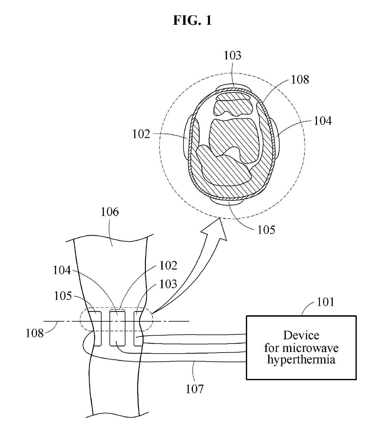
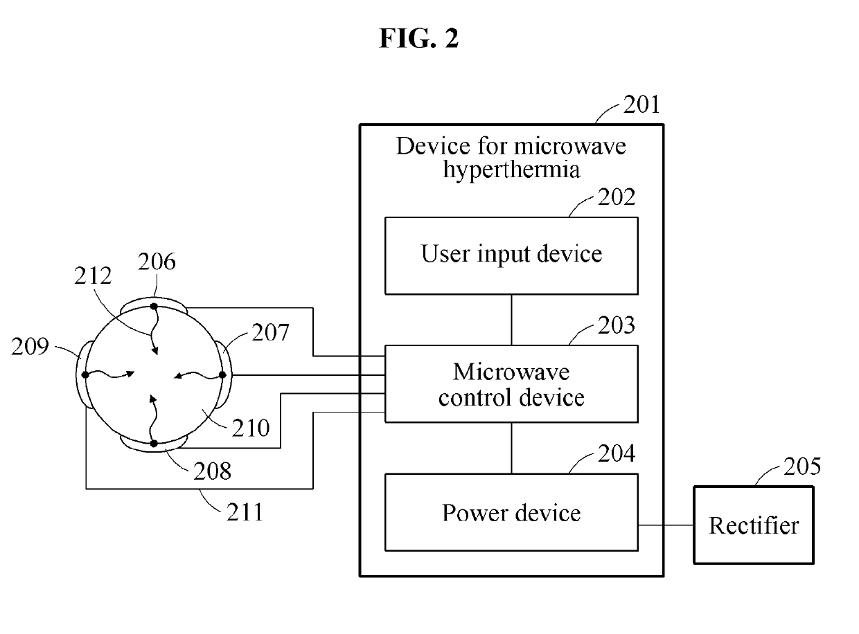
Provided is a device for microwave hyperthermia that may attach a flexible patch on the skin of a user based on a cross-section of a body tissue of the user, for example, a joint and muscle of a leg and an arm and may emit microwaves towards a plurality of points of the body tissue through the patch. The microwaves emitted toward the body tissue may have the same phase and maximum power. Accordingly, a maximum heat generation point may be generated in an area adjacent to the plurality of points. The device for microwave hyperthermia may move the maximum heat generation point by sequentially changing a phase and a direction of each of the microwaves. The device for microwave hyperthermia may uniformly distribute and maintain heat for treating pain and / or infection over the entire cross-section or a partial area. The device for microwave hyperthermia may be portable.

Description

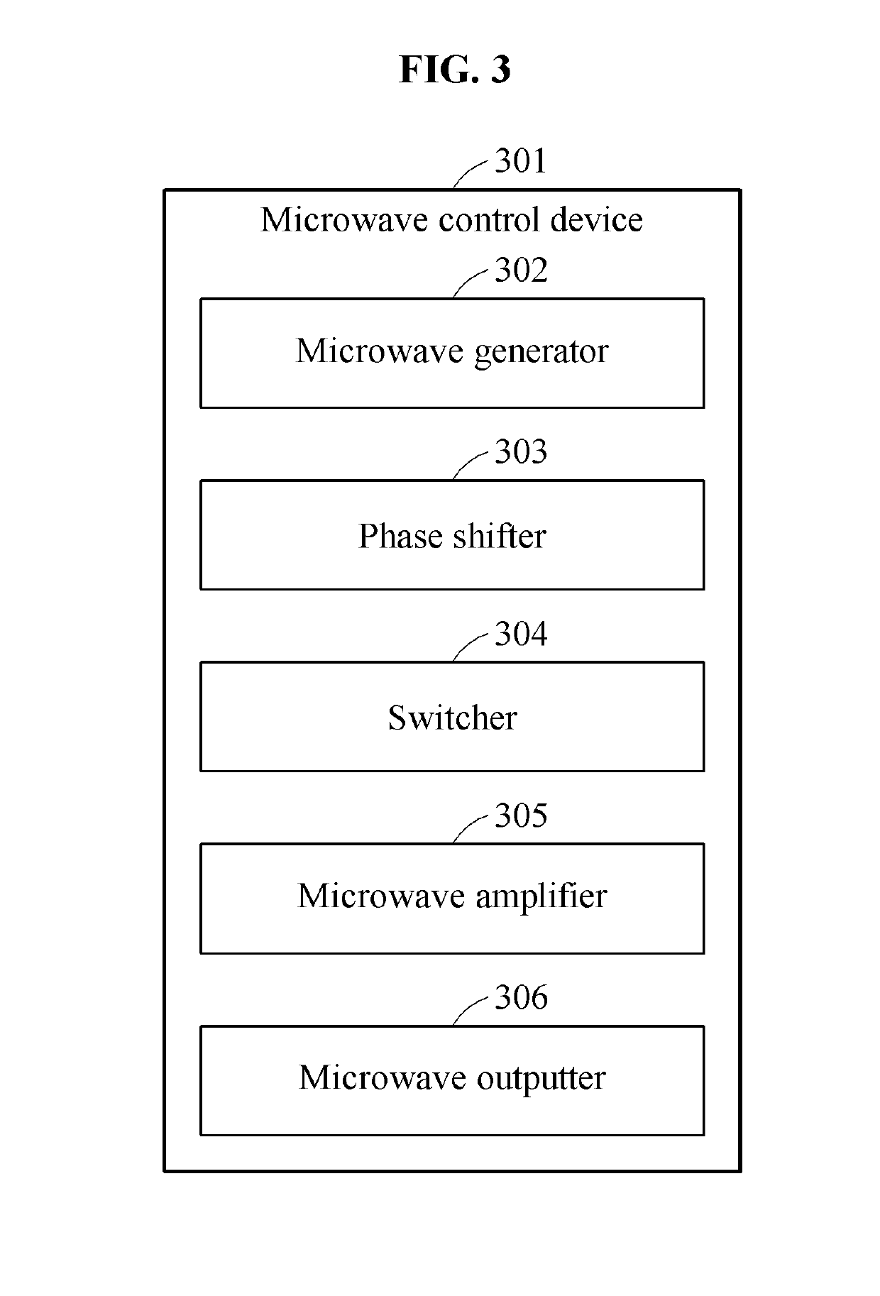
CROSS-REFERENCE TO RELATED APPLICATION(S)[0001]This application claims the priority benefit of Korean Patent Application No. 10-2017-0133989 filed on Oct. 16, 2017 and Korean Patent Application No. 10-2018-0055920 filed on May 16, 2018 in the Korean Intellectual Property Office, the disclosures of which are incorporated herein by reference for all purposes.BACKGROUND1. Field[0002]At least one example embodiment relates to a device for microwave hyperthermia, and more particularly, to a device for microwave hyperthermia that may treat pain and / or infection present over all of or a portion of a cross-section of a body tissue of a user by attaching a plurality of flexible microwave patches on the skin of the user based on the cross-section of the body tissue in a plurality of directions.2. Description of Related Art[0003]A thermotherapy device according to the related art may include elements configured to treat cancer and lesions, etc., and may induce microwaves toward lesions of a bo...

Claims


Application Information

Patent Timeline
IPC IPC(8): A61N5/02A61N1/40H01Q1/27H01Q9/04
CPCA61N5/025A61N1/403H01Q1/273H01Q9/0407H05B6/664H05B6/686A61F5/448A61N1/40A61F5/443
Inventor JEON, SOON IKKIM, JANG YEOLKIM, BO RASON, SEONG-HOLEE, KWANG JAE
Owner ELECTRONICS & TELECOMM RES INST
Learn More