Instrument for measuring workpiece, and machine tool

a technology for measuring instruments and workpieces, applied in the direction of instruments, mechanical measuring arrangements, program control, etc., can solve the problems of time-consuming and laborious tasks, inability to create measurement nc programs, and inability to select the desired measurement type from among multiple measurement types

Inactive Publication Date: 2019-04-18
MAKINO MILLING MASCH CO LTD
View PDF0 Cites 8 Cited by
  • Summary
  • Abstract
  • Description
  • Claims
  • Application Information

AI Technical Summary

Benefits of technology

[0012]Since the operator jog-feeds the measurement probe and teaches the measuring points directly for the measuring apparatus, it is

Problems solved by technology

However, when preparing a prototype or in the case of low-volume multi-product production, creating measurement NC programs is problematic from the viewpoint of cost effectiveness.
However, selecting the desired measurement type from among multiple measurement types is a time-consuming and labor-in

Method used


Image

  • Instrument for measuring workpiece, and machine tool
  • Instrument for measuring workpiece, and machine tool
  • Instrument for measuring workpiece, and machine tool

Examples


Embodiment Construction

[0040]Preferred embodiments of the present invention will be described below with reference to the attached drawings.

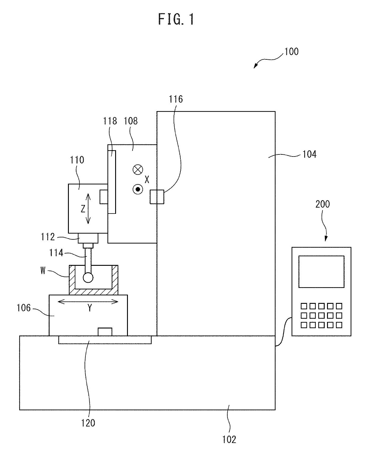
[0041]FIG. 1 shows an example of a machine tool to which the present invention is applied. In FIG. 1, a machine tool 100 according to a preferred embodiment of the present invention is configured as a vertical machining center and comprises a bed 102 as a base fixed on the floor of a factory, a table 106 on which a workpiece W can be fixed and which is provided on the upper surface of the front portion (the left side in FIG. 1) of the bed 102 and which is movable in the forwards and backwards directions or the Y-axis directions (the left and right directions in FIG. 1), a column 104 attached on the upper surface of the bed 102 on the rear end side (the right side in FIG. 1) of the bed 102, an X-axis slider 108 which is provided on the front surface of the column 104 and which is movable in the left and right directions or the X-axis directions (the directions perpendi...


PUM


Abstract

The present invention is configured such that: when an operator moves a spindle and a table relative to each other using a jog-feed means and when a measurement probe comes into contact with a workpiece fixed on the table, the coordinates of each feed axis are stored; the type of measurement performed by the operator is identified on the basis of the information concerning the feed axis used for moving said measurement probe, the moving direction of the feed axis, the number of times the measurement probe has come into contact with the workpiece, and the number of the jog-feed operation being currently performed by the operator; and the workpiece is measured on the basis of the stored coordinates of the respective feed axes.

Description

CROSS REFERENCE TO RELATED APPLICATIONS[0001]This application is a U.S. National phase patent application of International Patent Application No. PCT / JP2016 / 060826, filed Mar. 31, 2016, the contents of which are hereby incorporated by reference in the present disclosure in its entirety.FIELD OF THE INVENTION[0002]The present invention relates to an apparatus for measuring a workpiece capable of measuring a workpiece which is fixed on a table of a machine tool by a simple operation, and a machine tool.BACKGROUND OF THE INVENTION[0003]In machine tools, when a machine program is executed to machine a workpiece, it is necessary to provide the machine tool with a reference position of the workpiece. Thus, a reference point of the workpiece is measured using a measurement probe. A method for automatically executing a workpiece measurement operation by a measurement NC program is described in Patent Literature 1.[0004]Furthermore, Patent Literature 2 describes a semi-automatic measurement ...

Claims


Application Information

Patent Timeline
IPC IPC(8): B23Q17/20G01B5/012G05B19/401
CPCB23Q17/20G01B5/012G05B19/401G01B5/008G01B21/047G05B19/409G05B2219/50252G05B2219/50048G05B2219/50063
Inventor ISHII, KAZUNARIKAWAI, RIEKASAI, KOJISTANCU, ALEXANDRA FLORENTINA
Owner MAKINO MILLING MASCH CO LTD
Why Eureka
Try Eureka