
A multirotor aircraft with an airframe and at least one wing

a multi-rotor aircraft and airframe technology, applied in the direction of propellers, vertical landing/take-off aircraft, wings, etc., can solve the problems of increasing the complexity and weight of the underlying system, and limiting the use of such multi-rotor aircraft, so as to achieve safe and reliable transportation and facilitate passenger transportation

Active Publication Date: 2019-04-18
AIRBUS HELICOPTERS DEUT GMBH
View PDF0 Cites 15 Cited by
  • Summary
  • Abstract
  • Description
  • Claims
  • Application Information

AI Technical Summary

Benefits of technology

The present invention aims to provide a new multirotor aircraft that is safe, reliable, and suitable for transporting passengers in urban areas.

Problems solved by technology

However, the provision of tiltable thrust producing units results in high system complexity and system weight due to a need of controlling and surveillance of required active actuation means.
In particular, already the provision of such required active actuation means usually significantly increases an underlying system complexity and weight, so that respective maintenance costs of such multirotor aircrafts are generally very high, thus, limiting usage of such multirotor aircrafts at least mainly to military or governmental applications.
However, in particular for recently appearing multirotor aircraft concepts related to fast flying and / or passenger carrying multirotor aircrafts, such an inclining of the entire multirotor aircraft implies multiple technical problems and disadvantages, as described hereinafter.
Unfortunately, a higher degree of inclination automatically leads to higher drag which, in turn, limits an obtainable performance of the given multirotor aircraft.
However, when using a fixed attachment unit with a given multirotor aircraft, this typical maximum inclination angle would limit an achievable magnitude of a maximum achievable propulsive force, which is the horizontal component of a respectively generated thrust vector at a given inclination angle, thus, significantly limiting an overall achievable performance of the given multirotor aircraft.
Furthermore, the fixed attachment unit will directly propagate vibration of the thrust producing units into a respective passenger cabin of the given multirotor aircraft, which will further degrade the passenger comfort.
Moreover, when using a fixed attachment unit with a given multirotor aircraft, the latter requires additional manoeuvring engine overpower for enabling manoeuvring flight.
However, this will lead to a comparatively high power consumption.
As a consequence, a major disadvantage of all above-described conventional multirotor aircrafts consists in that they are not readily suitable for being used in currently emerging air transportation concepts.
However, for electrical flight only limited energy is available due to an underlying energy density of respectively provided electrical accumulators as electrical power sources.
As a consequence, the comparatively short range is generally limited to a maximum of half an hour of flight time.
Furthermore, during a typical transportation flight, a respective hovering time of the multirotor aircraft that is intended for use in such currently emerging transportation concepts will usually be very short and most of the time the multirotor aircraft will be performing forward flight.
However, such a suitable autorotation capability is very limited respectively impossible for all above-described conventional multirotor aircrafts.

Method used


Image

  • A multirotor aircraft with an airframe and at least one wing
  • A multirotor aircraft with an airframe and at least one wing
  • A multirotor aircraft with an airframe and at least one wing

Examples


Embodiment Construction

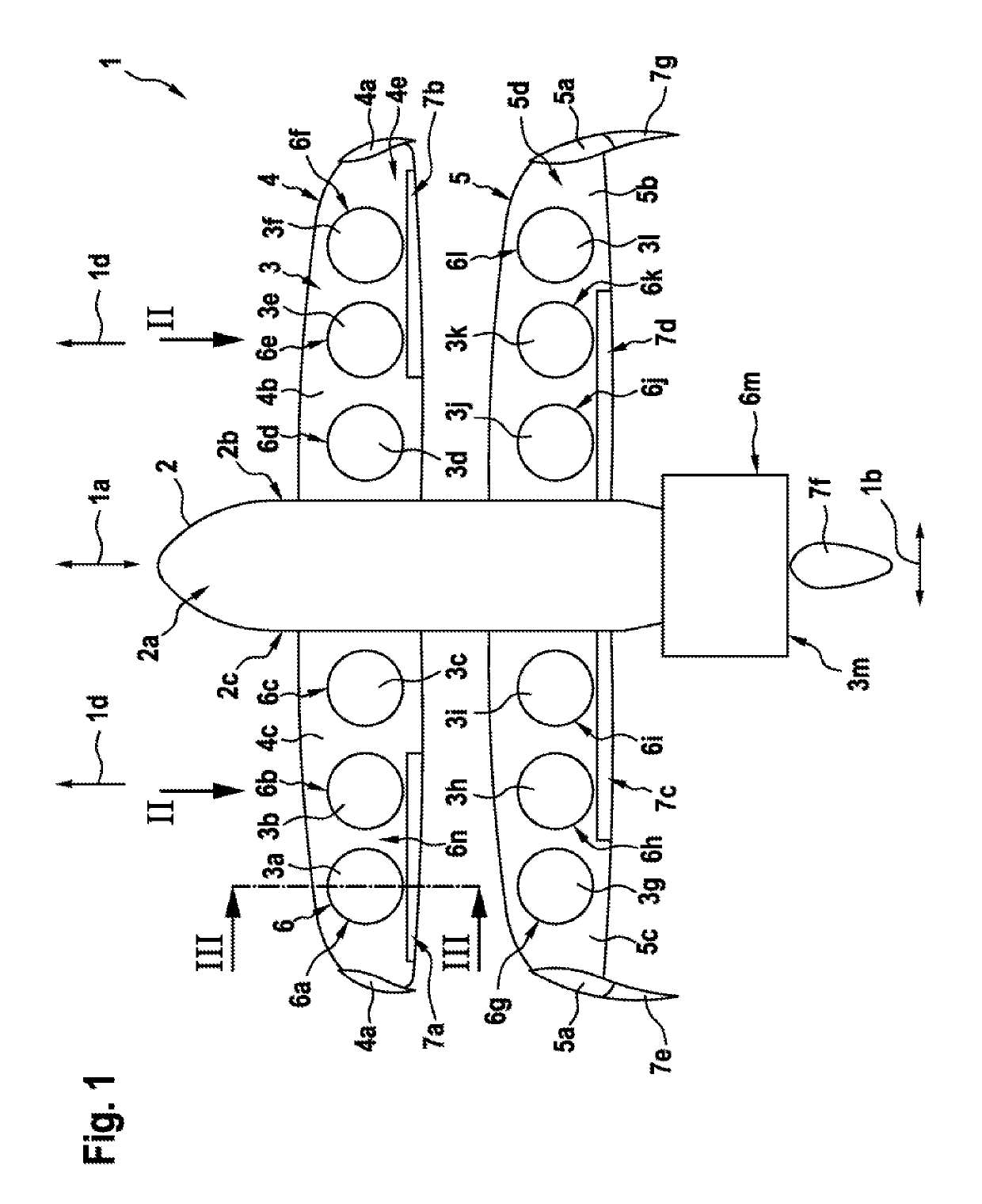
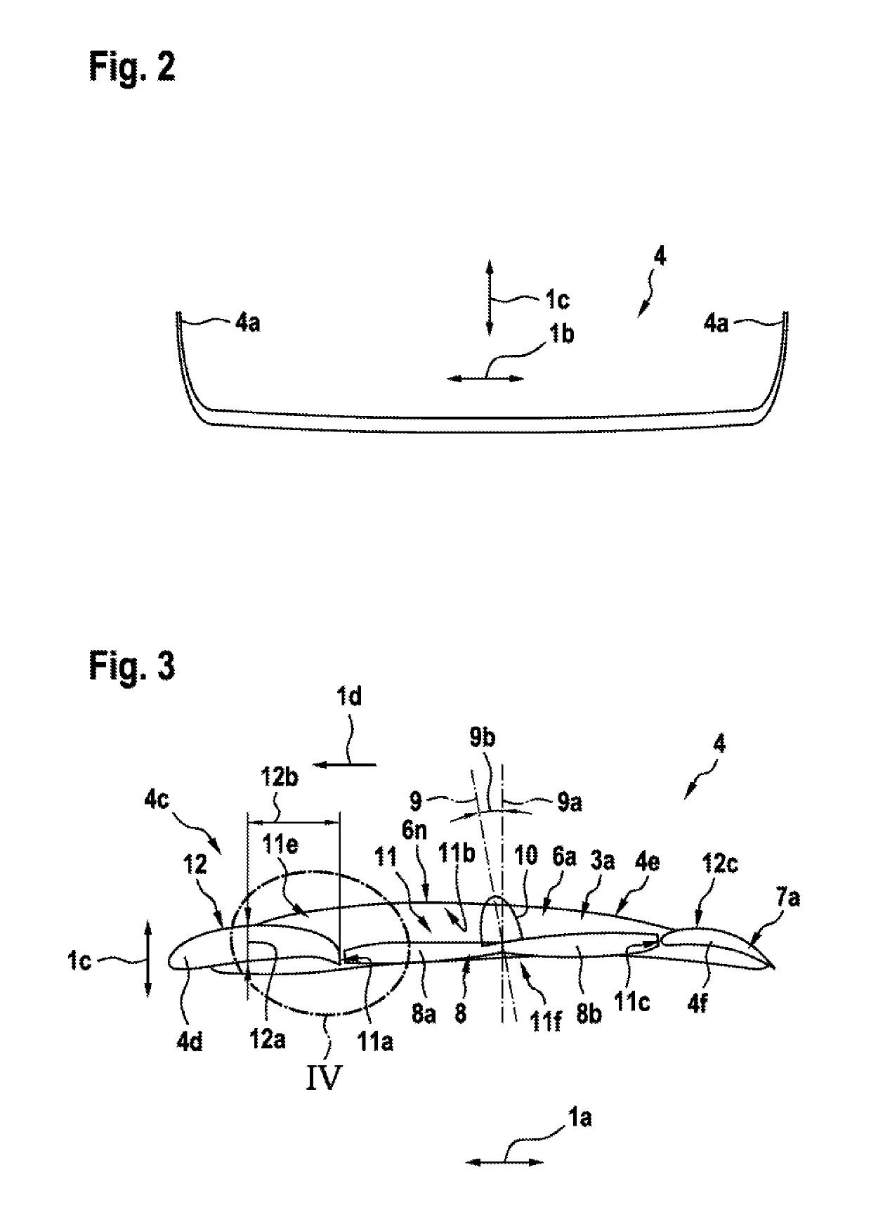
[0089]FIG. 1 shows a multirotor aircraft 1 with an aircraft airframe 2 according to the present invention. The airframe 2 defines a supporting structure of the multirotor aircraft 1 and illustratively has a board side 2b and a star board side 2c.

[0090]The airframe 2 has an extension in longitudinal direction 1a, an extension in lateral direction 1b as well as an extension in vertical direction (1c in FIG. 2) and preferably defines an internal volume 2a. According to one aspect, the internal volume 2a is at least adapted for transportation of passengers, so that the multirotor aircraft 1 as a whole is adapted for transportation of passengers. Alternatively, or in addition, the internal volume 2a may be adapted for transportation of products and goods. The internal volume 2a is preferably further adapted for accommodating operational and electrical equipment, such as e. g. an energy storage system that is required for operation of the multirotor aircraft 1. More specifically, the int...


PUM


Abstract

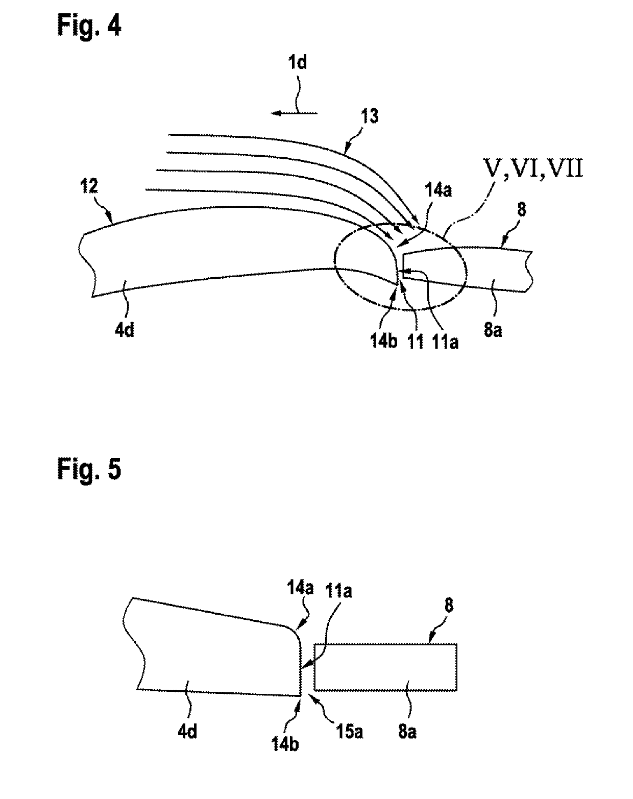
A multirotor aircraft with an airframe and at least one wing that is mounted to the airframe, the at least one wing being provided with at least four thrust producing units that are arranged in spanwise direction of the at least one wing, wherein each one of the at least four thrust producing units comprises at least one rotor assembly that is accommodated in an associated shrouding, the associated shrouding being integrated into the at least one wing, wherein the associated shrouding defines an air duct that is axially delimited by an air inlet region and an air outlet region, wherein the air inlet region exhibits in circumferential direction of the air duct at least two different aerodynamic profiles.

Description

CROSS-REFERENCE TO RELATED APPLICATIONS[0001]This application claims priority to European patent application No. EP 17400058.8 filed on Oct. 13, 2017, the disclosure of which is incorporated in its entirety by reference herein.BACKGROUND OF THE INVENTION(1) Field of the Invention[0002]The invention is related to a multirotor aircraft with an airframe and at least one wing that is mounted to the airframe, the at least one wing being provided with at least four thrust producing units for producing thrust in a predetermined direction.(2) Description of Related Art[0003]Various conventional multirotor aircrafts are known, e. g. from the documents EP 2 234 883 A1, U.S. Pat. No. 6,568,630 B2, U.S. Pat. No. 7,857,253 B2, U.S. Pat. No. 7,946,528 B2, and DE 10 2013 108 207 A1. Other multirotor aircrafts are also known from the state of the art, such as e. g. the Boeing CH-47 tandem rotor helicopter. Furthermore, so-called drones and, more particularly, so-called quad drones are also well-kno...

Claims


Application Information

Patent Timeline
Patent Type & Authority Applications(United States)
IPC IPC(8): B64C27/26B64C27/20B64C3/14B64C27/82
CPCB64C27/26B64C27/20B64C3/14B64C27/82B64C2003/148B64C2027/8236B64C27/12B64C27/22B64D27/16B64C29/0025B64C11/46B64C11/001
Inventor PFALLER, RUPERTKIESEWETTER, UWEMORES, SEBASTIANBEBESEL, MARIUS
Owner AIRBUS HELICOPTERS DEUT GMBH
Learn More