Plating apparatus and plating method

a technology of plating apparatus and plating film, which is applied in the direction of electrolysis process, electrolysis components, tanks, etc., to achieve the effect of preventing variations in the thickness of the formed plating film, satisfying the plating process, and stable current density

Active Publication Date: 2019-04-18
MURATA MFG CO LTD
View PDF0 Cites 4 Cited by
  • Summary
  • Abstract
  • Description
  • Claims
  • Application Information

AI Technical Summary

Benefits of technology

[0013]According to preferred embodiments of the present invention, electrolytic plating is performed while the object to be plated is passed through the workpiece passage region sandwiched between th

Problems solved by technology

The guidance unit may include a plating solution passage unit that allows the passag

Method used


Image

  • Plating apparatus and plating method
  • Plating apparatus and plating method
  • Plating apparatus and plating method

Examples


example 1

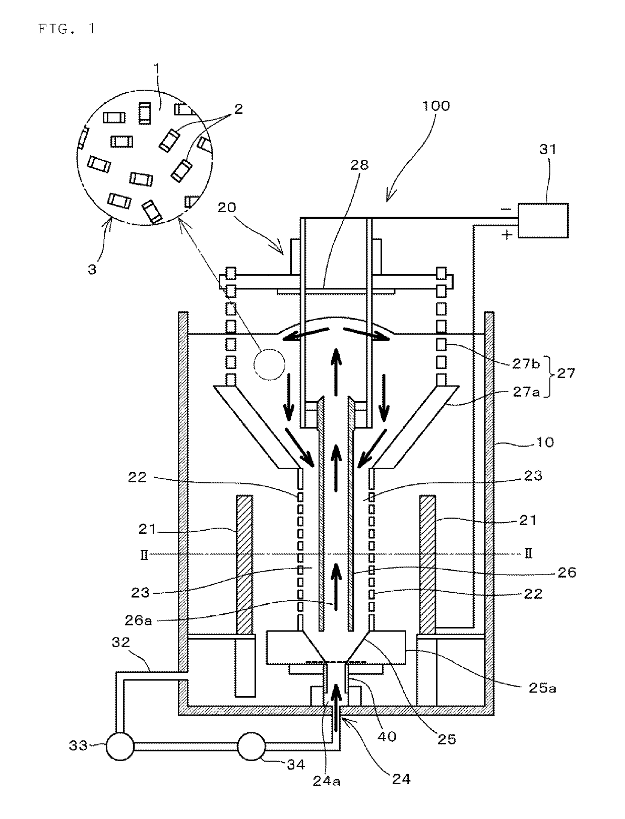
[0063]In Example 1 of a preferred embodiment of the present invention, a multilayer ceramic capacitor having a length of about 2.0 mm, a width of about 1.25 mm, and a thickness of about 1.25 mm, for example, was prepared as the object to be plated 2, and Ni plating and Sn plating were performed on the external electrodes of the multilayer ceramic capacitor. As described later, after the Ni plating was performed on the object to be plated 2, the Sn plating was performed on the object to be plated 2.

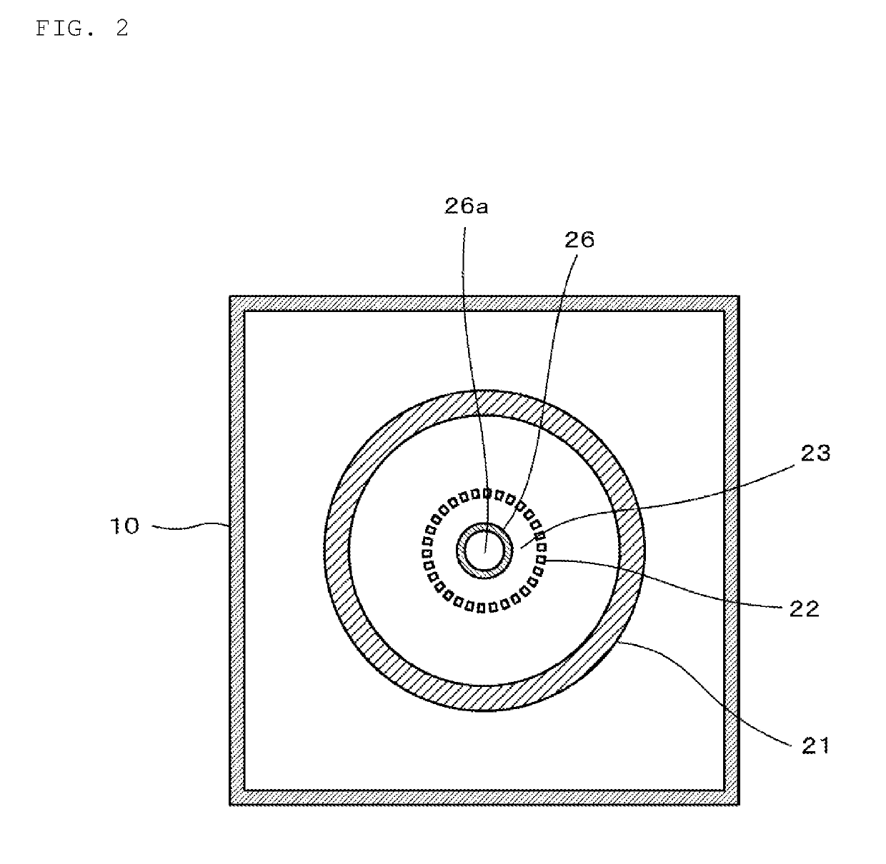
[0064]In the plating apparatus 100 having the configuration shown in FIGS. 1 and 2, a portion having liquid permeability in the cylindrical partition wall 22 was made of a mesh material of about 80 mesh, the diameter of the portion was about 70 mm, and the length of the portion was about 100 mm, for example. Portions which do not have the liquid permeability are located above and below the liquid-permeability portion, and the portions were defined by a pipe having the diameter of about 70 ...

example 2

[0083]In Example 2 of a preferred embodiment of the present invention, the Ni plating and the Sn plating were performed on the external electrodes of the multilayer ceramic capacitor having the length of about 4.5 mm, the width of about 3.2 mm, and the thickness of about 2.0 mm, for example, using the same plating apparatus 100 as that of Example 1. The presence or absence of cracking and chipping of the multilayer ceramic capacitor after the plating treatment was observed. The method for performing the Ni plating and the Sn plating was the same or substantially the same as Example 1.

[0084]Similarly to Example 1, the smoothing of the surface of the Sn film after the Sn plating was not observed, but the deposited Sn film remained. On the other hand, in the conventional barrel plating method in which the rotating barrel was used, the smoothing is produced at the ridgeline of the object to be plated, the Sn film was peeled off, and the inside external electrode was visible.

[0085]In eit...


PUM

PropertyMeasurementUnit
Liquid permeabilityaaaaaaaaaa
Diameteraaaaaaaaaa
Shapeaaaaaaaaaa

Abstract

A plating apparatus includes a plating tank and a plating unit that performs electrolytic plating on an object. The plating unit includes a workpiece passage region including a partition wall that allows passage of the plating solution but does not allow passage of the object, the workpiece passage region passing the object from above toward below, an injection unit that injects the plating solution from below toward above, a mixing unit that mixes the plating solution injected by the injection unit and the object to be plated passing through the workpiece passage region, an anode outside the workpiece passage region, a cathode inside the workpiece passage region including a hollow region through which a mixed fluid of the plating solution and the object to be plated passes from below toward above, and a guidance unit that guides the mixed fluid to the workpiece passage region.

Description

CROSS REFERENCE TO RELATED APPLICATIONS[0001]This application claims the benefit of priority to Japanese Patent Application No. 2016-119564 filed on Jun. 16, 2016 and is a Continuation Application of PCT Application No. PCT / JP2017 / 019748 filed on May 26, 2017. The entire contents of each application are hereby incorporated herein by reference.BACKGROUND OF THE INVENTION1. Field of the Invention[0002]The present invention relates to a plating apparatus and a plating method.2. Description of the Related Art[0003]In an electronic component, such as a chip multilayer capacitor, Ni plating and Sn Plating is typically performed on a surface of an external electrode included in the electronic component for the purpose of preventing solder corrosion and improving reliability of mounting by soldering.[0004]When plating, such as the Ni plating and the Sn plating, is performed on the electronic component, a barrel plating method is frequently used as disclosed in Japanese Patent Application La...

Claims


Application Information

Patent Timeline
IPC IPC(8): C25D17/02C25D17/18C25D17/00C25D5/08
CPCC25D17/02C25D17/18C25D17/001C25D5/08C23G3/00C25D5/12C25D5/48C25D17/22C25D17/28C25D21/08C25D17/002C25D5/611
Inventor HOSOKAWA, TAKAO
Owner MURATA MFG CO LTD
Why Eureka
Try Eureka