
Control System and Method for Operating a Plurality of Wind Turbines

a technology of control system and wind turbine, which is applied in the direction of adaptive control, process and machine control, instruments, etc., can solve the problems of insufficient local information, incongruous wind, and wind turbines located downwind can be subjected to increased load, so as to achieve enhanced control system

Active Publication Date: 2019-04-25
SIEMENS GAMESA RENEWABLE ENERGY SERVICE GMBH
View PDF0 Cites 4 Cited by
  • Summary
  • Abstract
  • Description
  • Claims
  • Application Information

AI Technical Summary

Benefits of technology

The invention aims to improve wind prediction by using estimated wind values from multiple wind turbines. By using these estimated wind values, a reliable wind prediction can be obtained from a prediction model to preventatively set the wind conditions for a future time point. Additionally, the method includes a process to account for changes in wind direction and speed, which allows for more accurate wind prediction. Overall, the invention improves wind prediction accuracy and helps optimize wind energy utilization.

Problems solved by technology

In wind parks composed of a plurality of wind turbines, there arises the problem that, depending on the wind direction, some wind turbines are located upwind in front of other wind turbines.
Downwind of the front wind turbines, inconsistent wind conditions occur, as a result of which the wind turbines located downwind can be subjected to increased loading.
For a reliable prediction, it is generally not sufficient to have local information about the current wind conditions in the case of a single wind turbine located upwind.
However, it is not entirely easy to obtain precise information about the current wind conditions.
The measurement values of an anemometer arranged on a wind turbine are normally falsified by the motion of the rotor, and are therefore not sufficiently reliable.
This, however, is demanding of resources and expensive.
It is likewise demanding of resources and expensive to equip a wind park with sensors that are separate from the wind turbines.

Method used


Image

  • Control System and Method for Operating a Plurality of Wind Turbines
  • Control System and Method for Operating a Plurality of Wind Turbines
  • Control System and Method for Operating a Plurality of Wind Turbines

Examples


Embodiment Construction

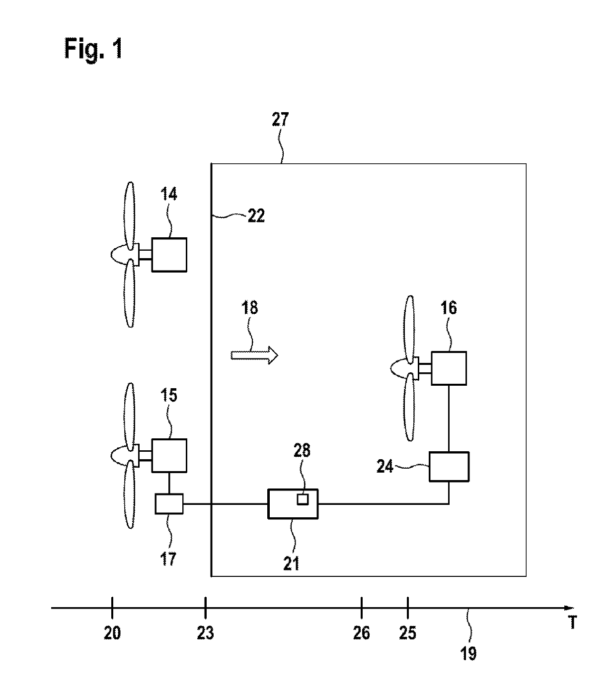
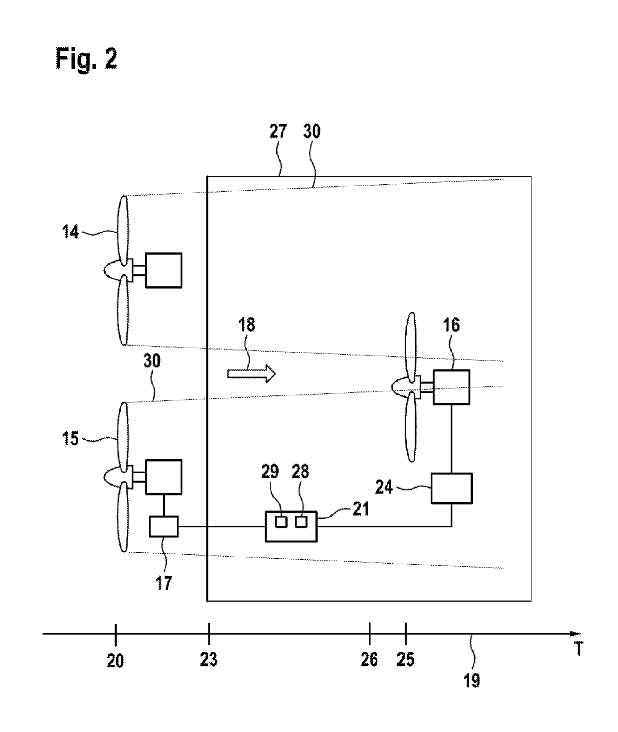
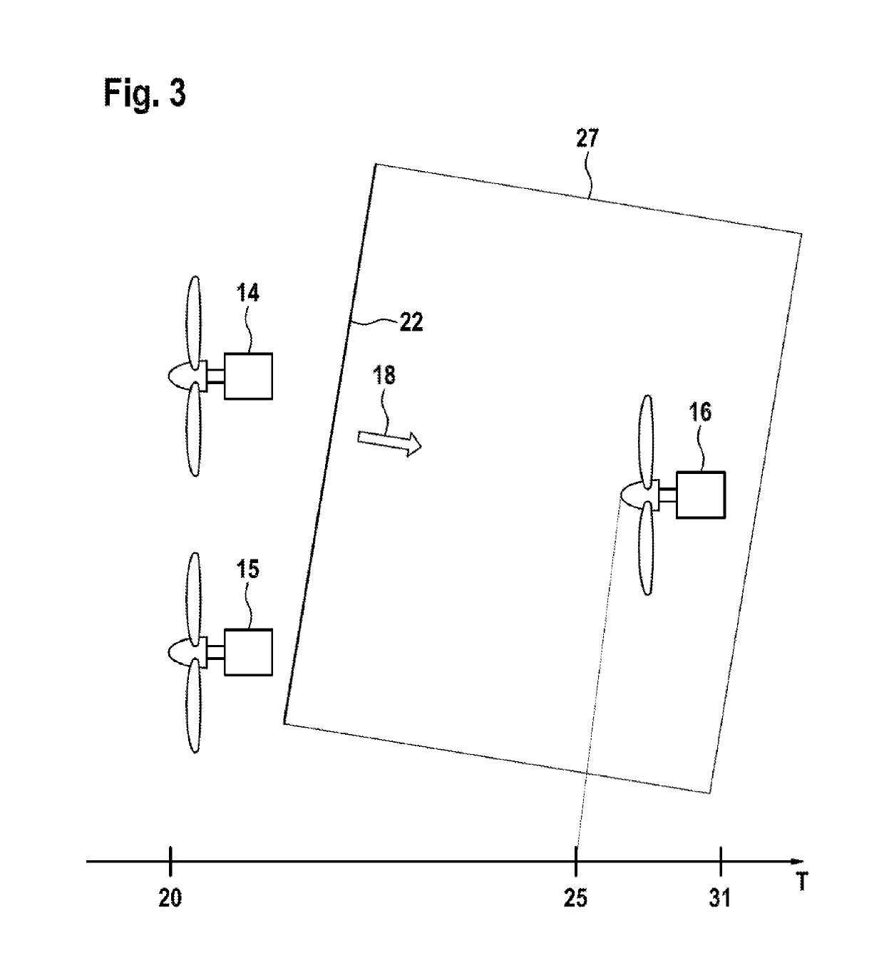
[0048]A wind park shown in FIG. 1 comprises a first wind turbine 14, a second wind turbine 15 and a third wind turbine 16. Each wind turbine 14, 15, 16 comprises a rotor, which is put into rotation by the wind and which drives a generator for the purpose of generating electrical energy. Each wind turbine 14, 15, 16, has a rated electrical energy output, which corresponds to the maximum electrical power the wind turbine can deliver in continuous operation. This maximum electrical power can be referred to as the “nominal output” of the wind turbine 14, 15, 16. The minimum wind speed necessary for the turbine to generate its nominal electrical output can be referred to as the “nominal wind speed” for the turbine 14, 15, 16. Each of the wind turbines 14, 15, 16 additionally comprises a wind estimator 17, which in FIG. 1 is represented only on the example of the wind turbine 15.

[0049]The wind estimators 17 are designed to determine, for each of the wind turbines 14, 15, 16, an estimated ...


PUM


Abstract

A method for operating a plurality of wind turbines, in which a first current estimated wind value is derived from operating parameters of a first wind turbine, and in which a second current estimated wind value is derived from operating parameters of a second wind turbine. A prediction model is applied to derive, from the first current estimated wind value and the second current estimated wind value, a wind prediction, applicable to a future time point, for a third wind turbine. The wind prediction is processed in a controller, in order to generate a control signal for the third wind turbine that is effective before the future time point. The invention additionally relates to an associated control system. The loading for particular wind turbines can be reduced in that the wind conditions are predicted for a future time point.

Description

BACKGROUND[0001]The invention relates to a control system and to a method for operating a plurality of wind turbines.[0002]In wind parks composed of a plurality of wind turbines, there arises the problem that, depending on the wind direction, some wind turbines are located upwind in front of other wind turbines. Downwind of the front wind turbines, inconsistent wind conditions occur, as a result of which the wind turbines located downwind can be subjected to increased loading.[0003]One approach for reducing the loads is to predict changes in the wind conditions for the wind turbines located downwind, such that, even before the changed wind conditions occur, the wind turbines can be brought into a state in which there is lesser loading, WO 03 / 01 2293 A2, DE 10 2010 063 396 A1, WO 2013 / 083131.[0004]For a reliable prediction, it is generally not sufficient to have local information about the current wind conditions in the case of a single wind turbine located upwind. Rather, it is desi...

Claims


Application Information

Patent Timeline
Patent Type & Authority Applications(United States)
IPC IPC(8): F03D7/04F03D1/00G05B13/04
CPCF03D7/045F03D1/00G05B13/048F05B2220/30F05B2260/80F05B2260/8211F05B2270/111F05B2270/20F05B2270/32F05B2270/404F05B2260/84F05B2270/321F03D17/00F03D7/00F03D7/048F05B2260/821Y02E10/72F05B2270/204
Inventor GEISLER, JENSSCHMUCK, JESSE BEN BENJAMIN
Owner SIEMENS GAMESA RENEWABLE ENERGY SERVICE GMBH
Learn More