Pivot mechanism with flexible elements for large-amplitude rotation guiding and pivot assembly comprising a plurality of said pivot mechanism

a technology of pivot assembly and flexible elements, which is applied in the direction of couplings, instruments, horology, etc., can solve the problems of considerable worsening of lateral stiffness and unfavorable long strokes

Active Publication Date: 2019-04-25
CSEM CENT SUISSE DELECTRONIQUE & DE MICROTECHNIQUE SA RECH & DEV
View PDF0 Cites 12 Cited by
  • Summary
  • Abstract
  • Description
  • Claims
  • Application Information

AI Technical Summary

Benefits of technology

[0010]In the pivot mechanism of the invention, no degree of internal freedom is sensitive to vibrations or creates a loss of rigidity when the pivot mechanism is pivoted relative to a position of equilibrium and the flexible connections are deflected.

Problems solved by technology

It also offers a clearance around its central shaft and proposes rigid couplings at the intermediate levels, which is highly unfavorable for a long stroke.
The pivot has non-coupled intermediary connections that firstly constitute internal degrees of freedom, which are highly unfavorable for resistance to vibrations, and secondly, due to the absence of coupling between the intermediary connections, the lateral stiffness is considerably worsened, particularly in a deflected position of the pivot.

Method used


Image

  • Pivot mechanism with flexible elements for large-amplitude rotation guiding and pivot assembly comprising a plurality of said pivot mechanism
  • Pivot mechanism with flexible elements for large-amplitude rotation guiding and pivot assembly comprising a plurality of said pivot mechanism
  • Pivot mechanism with flexible elements for large-amplitude rotation guiding and pivot assembly comprising a plurality of said pivot mechanism

Examples


Embodiment Construction

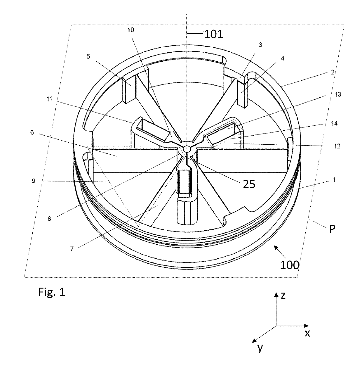
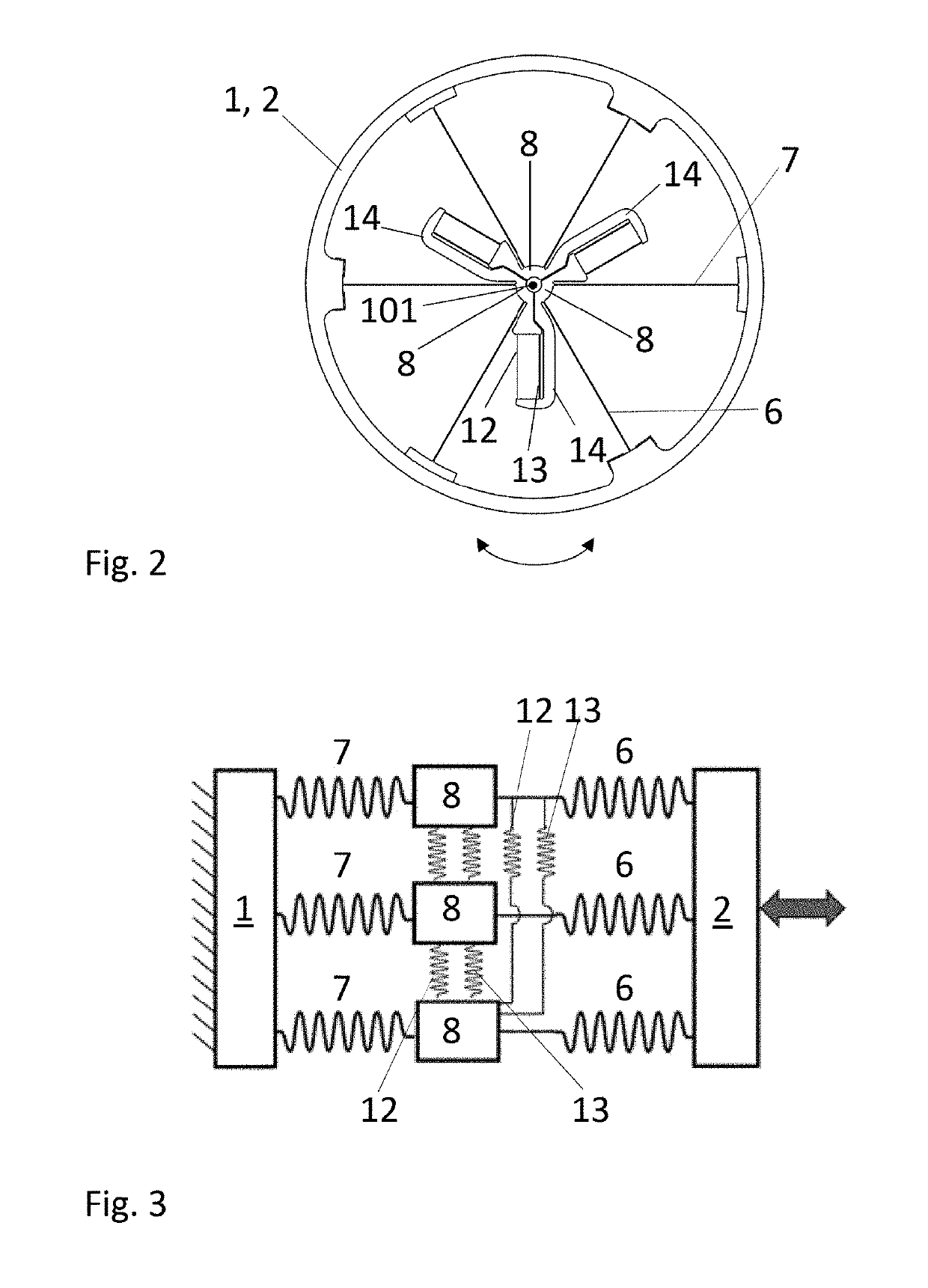
[0027]FIG. 1 shows an isometric view of a pivot mechanism 100 (also called “pivot” hereinafter) with radial symmetry and FIG. 2 shows a top view of the pivot 100 according to one embodiment. In particular, the pivot 100 comprises a mobile element 2 (taking the shape of a mobile ring in FIG. 1) connected to a fixed element 1 (also in the shape of a ring) through a number N of flexible (or articulated) connections 9. The fixed ring 1 is designed to be attached to a fixed base (not represented). The fixed base can be situated outside or inside the fixed ring 1. The value of N is 3 in the chosen example. In the embodiment of FIG. 1, each of the flexible connections 9 comprises a first main flexible blade 6 and a second main flexible blade 7, each of the main blades 6, 7 extending radially from the pivoting axis 101 of the pivot 100. The main blades 6, 7 are angularly spaced relative to each other by 60°, according to the example chosen, but could be spaced by another angle, for example ...


PUM


Abstract

Pivot mechanism for guiding in rotation, comprising a mobile element connected to a fixed element through flexible connections; with the flexible elements being configured to guide the mobile element according to a rotational movement in a plane, around a pivoting axis perpendicular to the plane; with each of the flexible connections comprising an intermediary junction provided with an expansion slot, the expansion slot being configured to expand during the rotation of the mobile element, so that the mobile element can pivot according to a second angular amplitude that is greater than a first angular amplitude achieved without said expansion slot; with the intermediary junctions being connected to one another by a coupling member; each of the coupling members being configured so as to prevent a movement out of the plane and a lateral movement in the plane of the mobile element. The pivot mechanism has a very high rotational amplitude.

Description

[0001]This application claims priority from European application EP17198118.6 filed Oct. 24, 2017, the content of which is incorporated by reference herein in its entirety.TECHNICAL FIELD[0002]The present invention concerns a pivot mechanism for precise rotational guiding and that allows a greater angular range to be covered. The present invention also concerns a pivot assembly comprising a plurality of pivot mechanisms.STATE OF THE ART[0003]Document EP0974761 describes a pivot with flexible elements allowing an angular stroke shorter than that of the proposed invention. This pivot offers a higher stiffness but exhibits many overconstraints. It provides a clearance around its central shaft, which is an advantage. It also proposes couplings at the intermediate levels, but the latter do not provide the same advantages as those of the present invention, namely: isostatics, low non-linearity of the stiffness, long stroke. It is possible to stack it like the present invention.[0004]EP225...

Claims


Application Information

Patent Timeline
Patent Type & Authority Applications(United States)
IPC IPC(8): F16C11/12
CPCF16C11/12F16C2326/05B64G1/66G01C19/22G12B5/00G04B17/045G04B31/06B64G1/44B64G1/222F16D3/005Y10T403/45Y10T403/54
Inventor COSANDIER, FLORENTSCHWAB, PHILIPPEKIENER, LIONEL
Owner CSEM CENT SUISSE DELECTRONIQUE & DE MICROTECHNIQUE SA RECH & DEV
Why Eureka
Try Eureka