

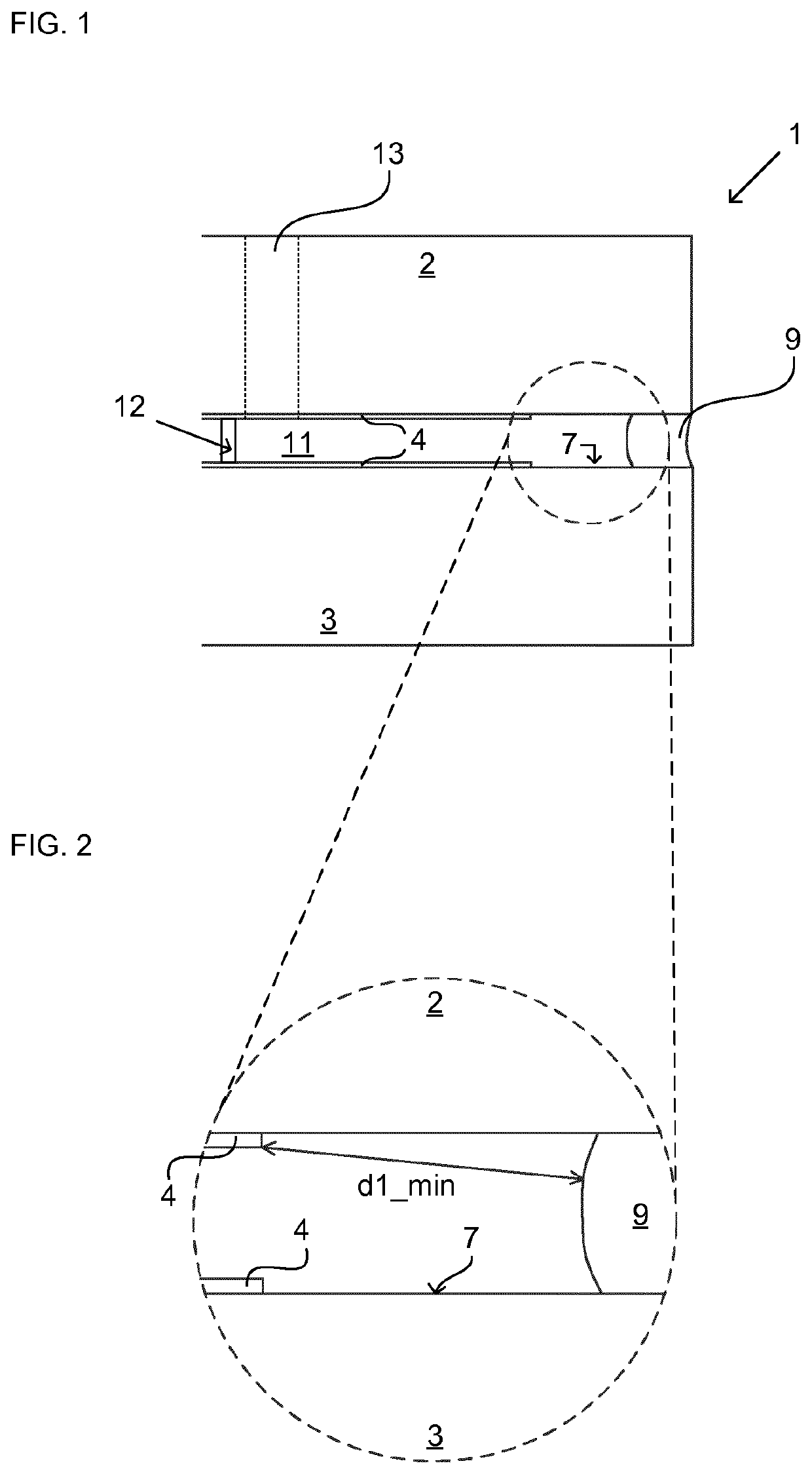
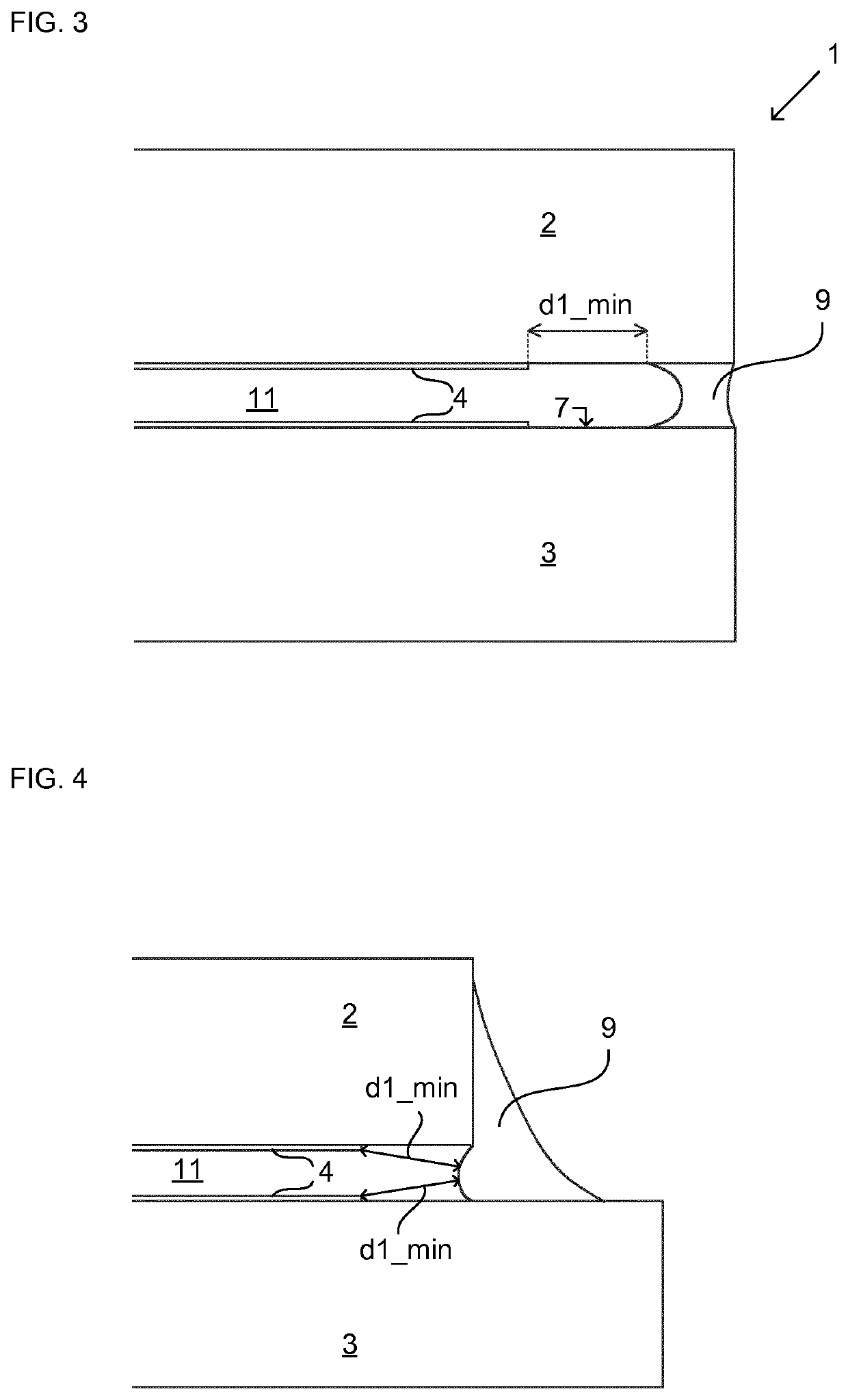
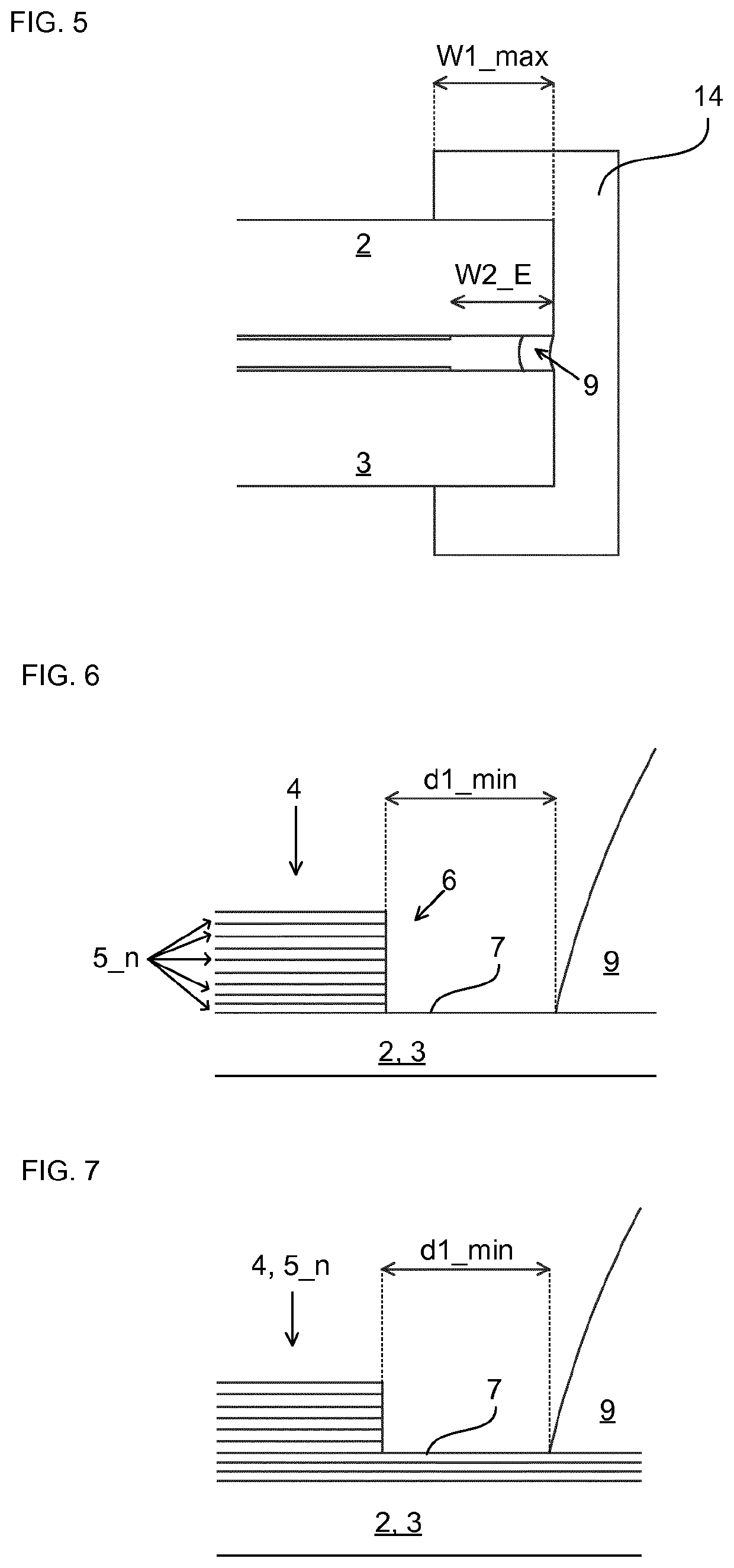
Vacuum insulated glazing unit having a separation distance between a side seal and a low emissivity coating, and associated methods of manufacturing same
a technology of insulating glazing unit and side seal, which is applied in the direction of climate change adaptation, building components, construction, etc., can solve the problems of obstructing visibility, slowing down the pressure in the vig unit, and affecting the quality and lifetime of the vig uni
- Summary
- Abstract
- Description
- Claims
- Application Information
AI Technical Summary
Benefits of technology
Problems solved by technology
Method used
Image

Examples
example 1
[0250]Comparable measurements of the emissivity of the low emissivity coating before and after thermal treatment by heating to 400 degrees Celsius for 20 minutes have been undertaken, both with and without low melting point glass being present. Table 1 shows emissivity data obtained from an assembly comprising a low emissivity coating arranged on a glass pane, with no low melting point glass being present. The assembly has been measured before thermal treatment and the emissivity data for this measurement is shown in row 1, from three different positions (A1-A3) on the low emissivity coating and with the associated maximum standard deviation (σ) of each measurement. The assembly has also been measured after thermal treatment at the same positions (A1-A3), and the data from these measurements and associated maximum standard deviation (σ) are presented in the second row of the table, marked by number 2. By inspection of the data in table 1 it can be seen that emissivity values remains...
example 2
[0253]A measure of sheet resistance of a low emissivity coating, measuring the electric loss within the coating, may provide indications of the level of emissivity of the coating, as the emissivity increases with increasing sheet resistance of the coating. In table 3, experimental sheet resistance data obtained by a non-contact and non-destructive measuring method from an assembly having a glass pane 2, 3 arranged with a low emissivity coating 4 and a low melting point glass frit as side sealing material 8 are presented. The low melting point glass 8 is peripherally arranged near the edge of the glass pane 2, 3 providing a substantially frame-like shape. The data is obtained in five different positions (P1, P2, P3, P4, P5) on the low emissivity coating 4 on the glass pane. Point 1-4 (P1, P2, P3 and P4) are located near the low melting point glass frit, approximately 10 mm from the low melting point glass frit, while point 5 (P5) is located near the centre of the low emissivity coati...
PUM
| Property | Measurement | Unit |
|---|---|---|
| separation distance | aaaaa | aaaaa |
| separation distance | aaaaa | aaaaa |
| separation distance | aaaaa | aaaaa |
Abstract
Description
Claims
Application Information