Eureka AIR delivers breakthrough ideas for toughest innovation challenges, trusted by R&D personnel around the world.

Breath analysis device

a breath analysis and breath technology, applied in the field of breath analysis devices, can solve the problems of slow chamber approach, inability to deliver breath-by-breath analysis, inaccurate sampling chambers,

Pending Publication Date: 2019-04-25
PNOE INC
View PDF8 Cites 12 Cited by
  • Summary
  • Abstract
  • Description
  • Claims
  • Application Information

AI Technical Summary

Benefits of technology

This invention is a low-cost and portable device that can accurately measure the amount of oxygen consumed and carbon dioxide produced during respiration. This allows for the accurate determination of an individual's metabolic rate, without relying on fixed values. The device does not use consumables, reducing costs, and can measure breath-by-breath analysis of oxygen and carbon dioxide production. It also has a communication means for convenient review of data on a mobile phone or other device.

Problems solved by technology

Sampling chambers are inaccurate because the sample of the new breath is mixed with the remains of previous breaths.
Moreover, the chamber approach is slower and struggles to deliver a breath-by-breath analysis.
Sampling chambers which measure averaged values cannot draw conclusions about the profile of carbon dioxide and oxygen.
When only the exhaled breath is able to be analysed as with sampling chambers, the Haldane transformation needs to be taken into account and this increases possibly the error of the measurement.
Such detection was not possible with the sampling chambers used in the prior-art.

Method used


Image

  • Breath analysis device
  • Breath analysis device
  • Breath analysis device

Examples


example 1

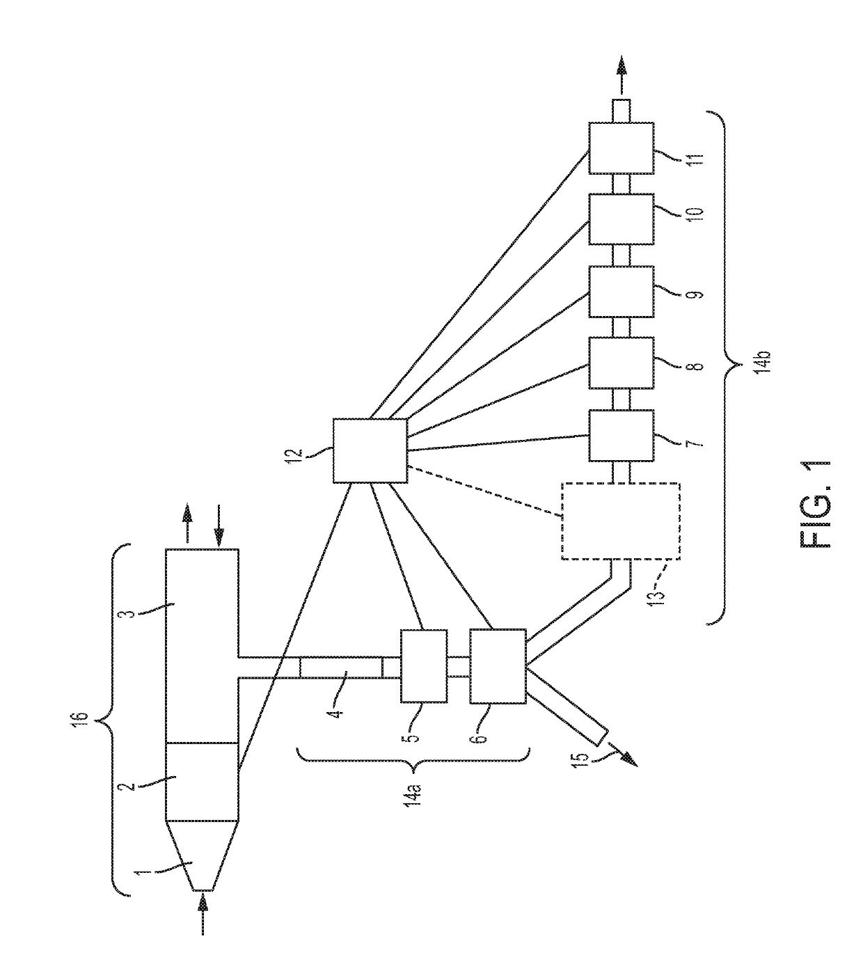
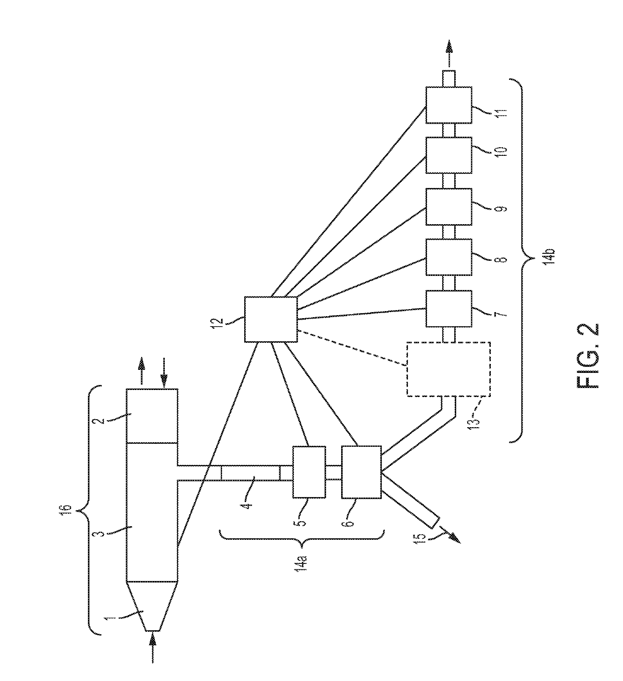
[0132]An example of a device according to the invention is shown schematically in FIG. 1. The device comprises a mouthpiece 1 connected to a flow sensor 2. Flow sensor 2 measures the flow rate of exhaled and inhaled breath when a user exhales and inhales into the mouthpiece. In the device shown, a non-rebreathing valve is not present; a user may inhale as well as exhaling into the device. When inhaling, ambient air is drawn through the outlet at the end of the primary pathway. Air may thus pass through the primary pathway in two directions.

[0133]The primary pathway 16 is formed of the mouthpiece 1, the flow sensor 2, and part of a T-shaped connector 3 which joins the primary pathway to the secondary pathway 14. The T-shaped connector also forms part of the secondary pathway. A portion of the exhaled breath is sampled from the periphery of the primary pathway and is guided along the secondary pathway.

[0134]The sample of exhaled breath is drawn through the secondary pathway at a const...

example 2

Time Data

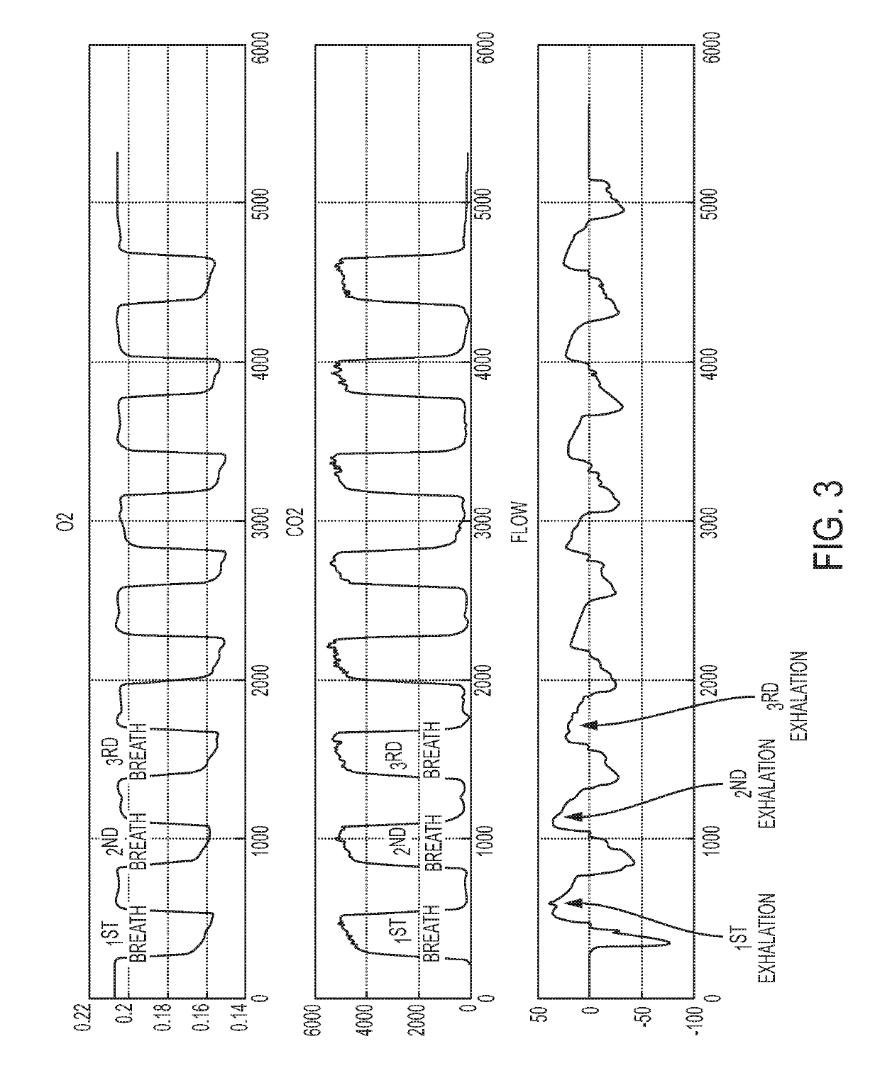
[0140]Plots over time (in seconds) of the oxygen, carbon dioxide and flow measurements obtained by a device of the invention on a breath-by-breath basis are shown in FIG. 3. Oxygen is measured in O2 (%), carbon dioxide is measured in ppm and flow is measured in L / min.

example 3

Clinical Validation of Device

[0141]A device in accordance with the invention was validated in a clinical setting. Metabolism of 25 healthy subjects was measured simultaneously by a gold-standard device and by a device in accordance with the invention, in order to assess the accuracy of the device described herein. Values for VCO2, VO2 and energy expenditure were measured for each subject. FIGS. 4 to 6 show Bland-Altman plots which demonstrate the difference in the measured values of VCO2 energy expenditure (EE) and VO2, between a gold-standard metabolic assessment device and an indirect calorimeter device as described herein. From FIGS. 4 to 6 it can be concluded that the device according to the invention has medical grade accuracy according to the norms of the industry.


PUM

PropertyMeasurementUnit
RHaaaaaaaaaa
thermal conductivityaaaaaaaaaa
humidityaaaaaaaaaa

Abstract

Provided herein is a portable breath analysis device for analysing breath of a subject to identify levels of gases such as oxygen and carbon dioxide. The device fmds use in, for example, monitoring the health of subjects. Also provided herein are methods of analysing breath of a subject using the device.

Description

CROSS REFERENCE TO RELATED APPLICATION[0001]This application claims the benefit to EP17386006.5 filed Feb. 21, 2017 and GB1606292.9 filed Apr. 12, 2016, which is incorporated by reference in its entirety.FIELD OF THE INVENTION[0002]This invention relates to a device for measurement of breath. In particular, but not exclusively, the present invention relates to a portable breath analysis device suitable for use in indirect calorimetry. The invention also relates to a method of analysing a subject's breath.BACKGROUND OF THE INVENTION[0003]Breath analysis has gained a lot of interest during recent years since it is a non-invasive technique that has many promising results. Since ancient times, physicians have been aware of the relationship between the odour of a person's breath and certain diseases. Since then it has been recognised that breath could give insight into physiological and pathophysiological processes of the human body (see, for example, W. Ma, W, Liu X and J. Pawliszyn, “A...

Claims


Application Information

Patent Timeline
Patent Type & Authority Applications(United States)
IPC IPC(8): G01N33/497A61B5/083A61B5/08A61B5/097A61B5/087
CPCG01N33/497A61B5/0833A61B5/0803A61B5/097A61B5/0836A61B5/087
Inventor ATSALAKIS, APOSTOLOS
Owner PNOE INC
Why Eureka
Eureka Blog
Learn More