
Mixing method and mixing apparatus for particle agglutination

a mixing apparatus and mixing method technology, applied in the field of mixing method and mixing apparatus for particle agglutination, can solve the problems of lack of standardization process of blood typing test, immediate centrifugal method of test tube, laborious and laborious consumption, etc., to reduce testing steps and testing time, and improve operation convenience

Inactive Publication Date: 2019-04-25
DELTA ELECTRONICS INC
View PDF3 Cites 0 Cited by
  • Summary
  • Abstract
  • Description
  • Claims
  • Application Information

AI Technical Summary

Benefits of technology

The present invention provides a mixing method and apparatus for particle agglutination with advantages of reducing testing steps and time, and improving operation convenience. The channel structure features a diverging channel, accommodating recess, and air chamber that communicate with the diverging channel, allowing a negative pressure to draw the testing materials from the accommodating recess to the air chamber. The depth of the diverging channel is gradually increasing, allowing the testing materials to mix with each other in the channel. The apparatus fabrication cost is low, and can be operated without any centrifugal apparatus. Users can conveniently observe whether the agglutination phenomenon occurs in the area of the diverging channel.

Problems solved by technology

However, the test-tube immediate centrifugal method has some problems, such as lack of standardization process of blood typing test and intensive time and labor consumption.
However, this solid microplate method is only a semi-quantitative test for a rough estimation.
In addition, the solid microplate method also suffers the disadvantages of long testing time and the necessary pretreatment of the specimen.
However, the detection card with the gel columns used in the gel column agglutination method is expensive, and a centrifuge is required in the gel column agglutination method.
In addition, the gel column agglutination method also has the deficiencies of long testing time and the necessary pretreatment of the specimen.

Method used


Image

  • Mixing method and mixing apparatus for particle agglutination
  • Mixing method and mixing apparatus for particle agglutination
  • Mixing method and mixing apparatus for particle agglutination

Examples


Embodiment Construction

[0036]Reference will now be made in detail to the present embodiments of the invention, examples of which are illustrated in the accompanying drawings. Wherever possible, the same reference numbers are used in the drawings and the description to refer to the same or like parts.

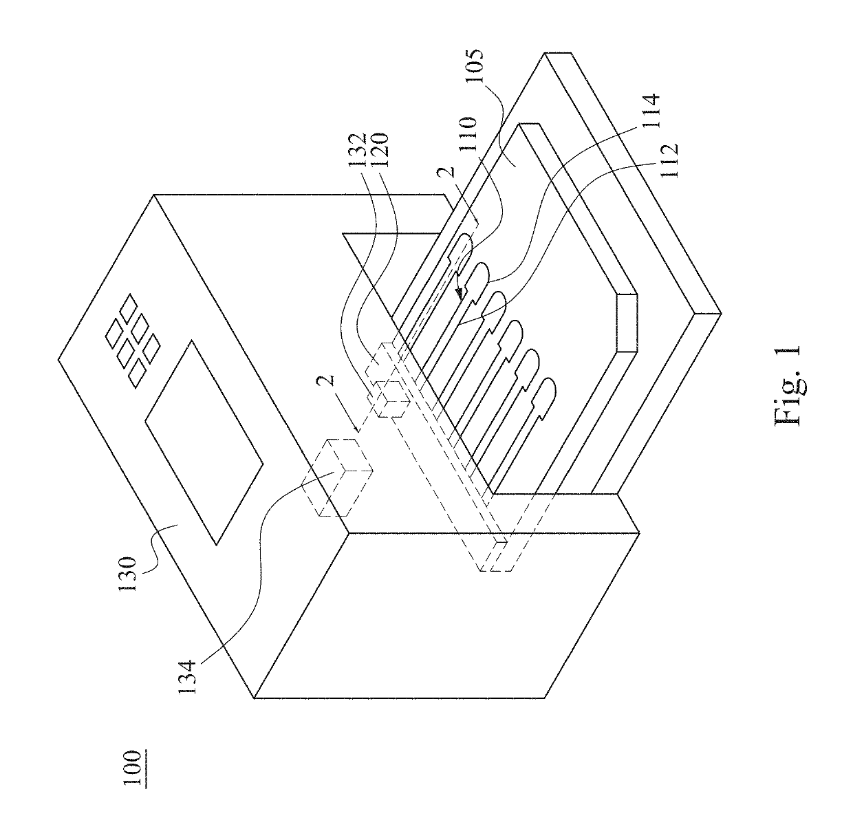
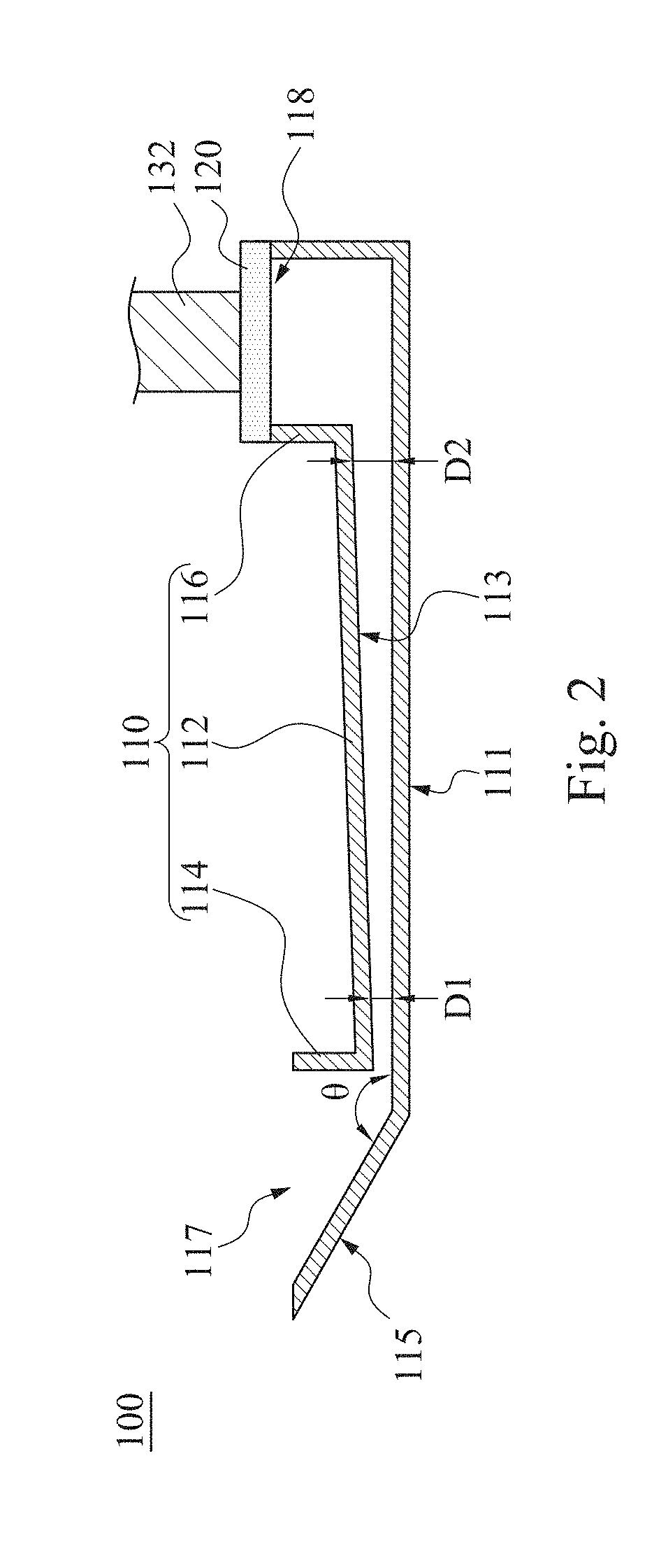
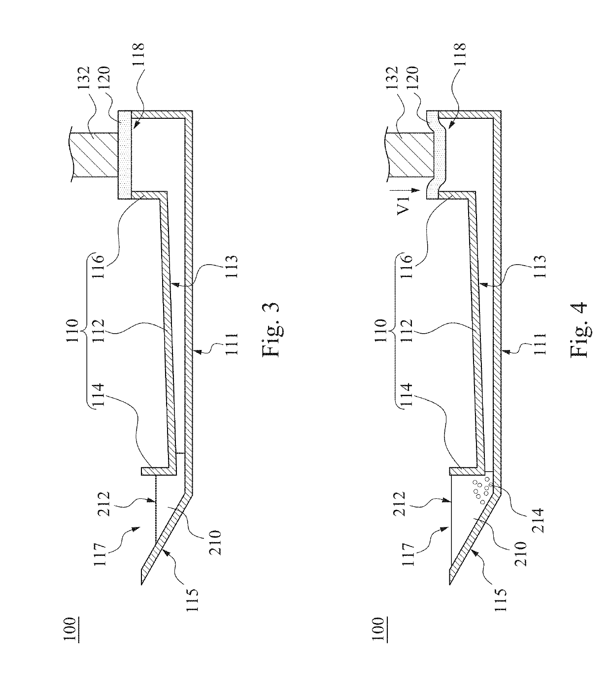
[0037]FIG. 1 is a perspective view of a mixing apparatus 100 for particle agglutination according to one embodiment of the present invention. FIG. 2 is a cross-sectional view of the mixing apparatus 100 for particle agglutination taken along line 2-2 shown in FIG. 1. As shown in FIG. 1 and FIG. 2, the mixing apparatus 100 for particle agglutination includes a card 105, a channel structure 110, and a flexible layer 120. The channel structure 110 is embedded in the card 105. The channel structure 110 has a diverging channel 112, and two ends of the channel structure 110 respectively have an accommodating recess 114 and an air chamber 116. The channel structure 110 may be integrally formed as one single piece, bu...


PUM

PropertyMeasurementUnit
velocityaaaaaaaaaa
velocityaaaaaaaaaa
velocity V1aaaaaaaaaa

Abstract

A mixing method for particle agglutination includes the following steps of: dropping testing materials into an accommodating recess at one end of a channel structure; pressing a flexible layer on the other end of the channel structure; and releasing the flexible layer to an initial position after pressing the flexible layer such that a negative pressure is generated by an air chamber that is covered by the flexible layer and draws the testing materials that are in the accommodating recess to move toward the air chamber along a diverging channel of the channel structure. The testing materials are mixed with each other in the diverging channel, in which the depth of the diverging channel is gradually increased from the accommodating recess to the air chamber.

Description

RELATED APPLICATIONS[0001]This application claims priority to Taiwan Application Serial Number 106136750, filed Oct. 25, 2017, which is herein incorporated by reference.BACKGROUNDField of Invention[0002]The present invention relates to a mixing method and a mixing apparatus for particle agglutination.Description of Related Art[0003]In general, there are three blood types testing methods to mix blood and an antibody, including a test-tube immediate centrifugal method, a solid microplate method and a gel column agglutination method. In the test-tube immediate centrifugal method, blood and antibody are mixed in a test tube. If the blood is agglutinative, the blood is gathered to form blood agglutination that precipitates at the bottom of the test tube. However, the test-tube immediate centrifugal method has some problems, such as lack of standardization process of blood typing test and intensive time and labor consumption.[0004]Moreover, in the solid microplate method, blood and an ant...

Claims


Application Information

Patent Timeline
Patent Type & Authority Applications(United States)
IPC IPC(8): G01N33/53G01N15/14B01L3/00G01N33/543B01F13/00G01N1/38G01N33/80
CPCG01N33/5304G01N15/1484B01L3/502792G01N33/54333B01F13/0064G01N1/38G01N33/80G01N2015/1081B01L2300/069B01L2400/0487B01L3/502761B01F31/651B01F33/3017G01N2015/1028
Inventor CHIOU, CHI-HANCHEN, KUAN-YUCHANG, CHING-YU
Owner DELTA ELECTRONICS INC
Learn More