Received signal alarm and alarm value removal test algorithm suitable for optical module

A technology for receiving signals and alarm values, which is applied in the field of optical communication, can solve the problems of not being able to adapt to the operation requirements of optical module automatic test software, difficult to control the attenuation speed of received light and test accuracy, and many steps for calculating alarm values, so as to reduce the number of receiving errors. Test steps for alarm values, improve test efficiency, and reduce the effect of test steps

Active Publication Date: 2019-07-05
SHENZHEN OPTIC KING TECH
View PDF5 Cites 2 Cited by
  • Summary
  • Abstract
  • Description
  • Claims
  • Application Information

AI Technical Summary

Problems solved by technology

This test algorithm makes the calculation steps of the alarm value numerous, it is difficult to control the attenuation speed of the received light and the test accuracy, the response speed is slow, and it cannot adapt to the operation requirements of the optical module automatic test software

Method used


Image

  • Received signal alarm and alarm value removal test algorithm suitable for optical module
  • Received signal alarm and alarm value removal test algorithm suitable for optical module
  • Received signal alarm and alarm value removal test algorithm suitable for optical module

Examples


Embodiment 1

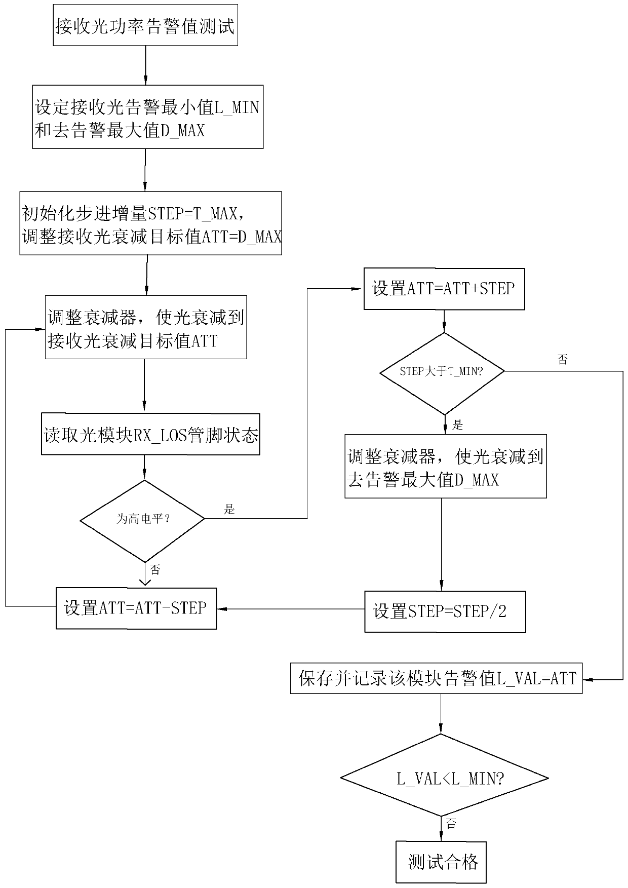
[0039] refer to figure 1 and figure 2 , which is a test algorithm for receiving signal alarm and de-alarm value disclosed by the present invention, the specific steps of the test algorithm are:

[0040] S01: Set the minimum allowable receiving light alarm value to L_MIN, set the allowable maximum receiving light de-alarm value to D_MAX, set the maximum receive light power increment T_MAX, set the receive light power minimum increment T_MIN, define The measured optical module RX_LOS is at a high level when the received optical power is in the alarm state, and the measured optical module RX_LOS is at a low level when the received optical power is in the alarm state;

[0041]S02: Test the alarm value of the received signal, initialize the step increment STEP of the optical attenuation value to be equal to the maximum increment of the received optical power T_MAX, and initialize the target value of the received optical attenuation ATT to be equal to the maximum value D_MAX of th...

Embodiment 2

[0059] In one embodiment, an optical module device is provided. The optical module device is composed of an optoelectronic device, a functional circuit, and an optical interface. The receiving end then converts the optical signal into an electrical signal. When the optical module device is tested, a test algorithm for receiving signal alarm and de-alarm value is implemented.

[0060] The specific steps of the test algorithm are:

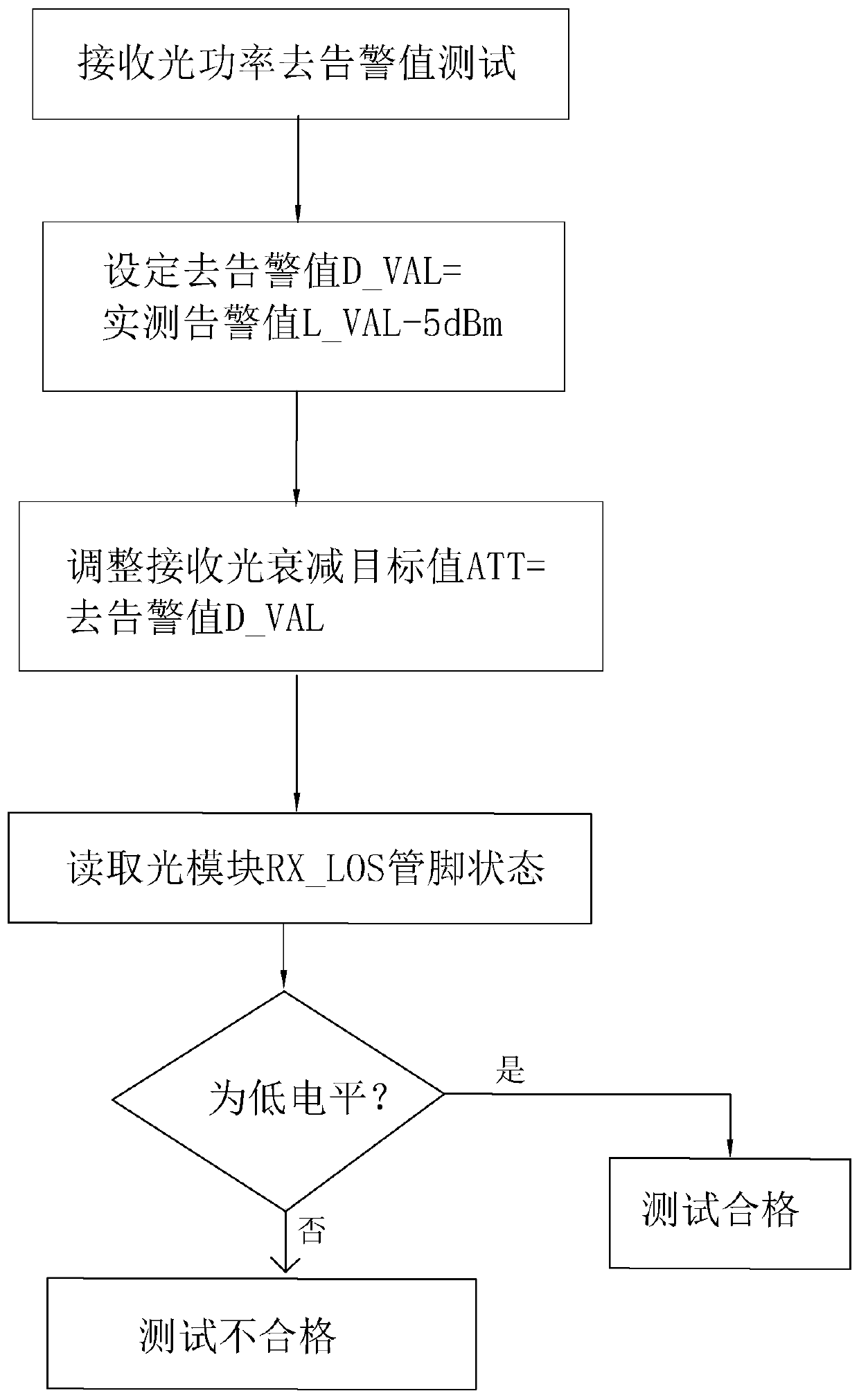
[0061] S1: After accurately measuring the measured alarm value L_VAL, set the de-alarm value D_VAL equal to the measured alarm value L_VAL-5dBm;

[0062] S2: Adjust the attenuation of the optical attenuator so that the received light attenuation target value ATT is equal to the alarm value D_VAL;

[0063] S3: Read the state of the RX_LOS pin of the optical module under test, and judge whether it is low level;

[0064] S4: If the state of the RX_LOS pin of the tested optical module is low level, the test is passed; if the state of the RX_LOS pin of...

Embodiment 3

[0066] In one embodiment, a storage medium is provided, on which a computer program is stored, and when the computer program is executed by a processor, the following steps are implemented:

[0067] The specific steps of the test algorithm are:

[0068] S1: After accurately measuring the measured alarm value L_VAL, set the de-alarm value D_VAL equal to the measured alarm value L_VAL-5dBm;

[0069] S2: Adjust the attenuation of the optical attenuator so that the received light attenuation target value ATT is equal to the alarm value D_VAL;

[0070] S3: Read the state of the RX_LOS pin of the optical module under test, and judge whether it is low level;

[0071] S4: If the state of the RX_LOS pin of the tested optical module is low level, the test is passed; if the state of the RX_LOS pin of the tested optical module is not low level, the test is failed.


PUM


Abstract

The invention relates to the field of optical communication, and aims to provide a received signal alarm and alarm value removal test algorithm applicable to an optical module, which is characterizedby comprising the following steps of: after accurately measuring an actual measurement alarm value L _ VAL, setting the alarm value D _ VAL to be equal to the actual measurement alarm value L _ VAL-5dBm; adjusting the attenuation amount of the optical attenuator, and enabling the received optical attenuation target value ATT to be equal to the alarm removing value D _ VAL; reading the RX _ LOS pinstate of the tested optical module, and judging whether the optical module is at a low level or not; if the RX _ LOS pin state of the tested optical module is a low level, qualifying the test; and ifthe RX _ LOS pin state of the tested optical module is not the low level, unqualifying the test. The method is suitable for testing the receiving end of the optical module.

Description

technical field [0001] The invention relates to the field of optical communication, more specifically, it relates to a receiving signal alarm and de-alarm value test algorithm suitable for optical modules. Background technique [0002] Usually, in the optical module products, an RX_LOS pin is designed in the interface, and the information of whether the received signal is lost is obtained by monitoring the RX_LOS state in the hardware circuit design. [0003] RX_LOS (ReceiveLossofSignalAlarm, received signal loss alarm), RX_LOS function is to directly reflect whether the received signal is normal, when the received signal is greater than the alarm value, it means that the signal is not lost, RX_LOS=0 (low level), when the received signal is less than the alarm value When the signal is lost, RX_LOS=1 (high level). In Ethernet, when the system detects a change in the RX_LOS state, it will quickly report the RX_LOS state to the processing system, and then the processing system...

Claims


Application Information

Patent Timeline
Patent Type & Authority Applications(China)
IPC IPC(8): H04B10/079
CPCH04B10/07953H04B10/07955
Inventor 刘萍刘平
Owner SHENZHEN OPTIC KING TECH
Why Eureka
Try Eureka