Moving Body Tracking Device, Moving Body Tracking Method, and Moving Body Tracking Program
a technology of moving body and tracking device, which is applied in the direction of image analysis, image enhancement, instruments, etc., can solve the problems of difficult to track the moving body without relying, the velocity and trajectory of the ball may be difficult to be recorded without relying, and the features of the moving body are not outstanding, so as to achieve the effect of effective training of the player, easy to take, and high accuracy
- Summary
- Abstract
- Description
- Claims
- Application Information
AI Technical Summary
Benefits of technology
Problems solved by technology
Method used
Image
Examples
embodiment 1
[0051]A moving body tracking device according to this embodiment is a device that tracks a moving body using an image. The moving body tracking device according to this embodiment is suitably employed for a device that tracks a moving body having few features outstanding in appearance such as a color, a shape, and a location of parts that moves in accordance with the law of motion in a predetermined field, such as tracking the movement of a ball in the ball game or the like such as the table tennis, the golf, the baseball, and the volleyball, with high accuracy. This is an example, and the application is not limited to only the athletic competition.
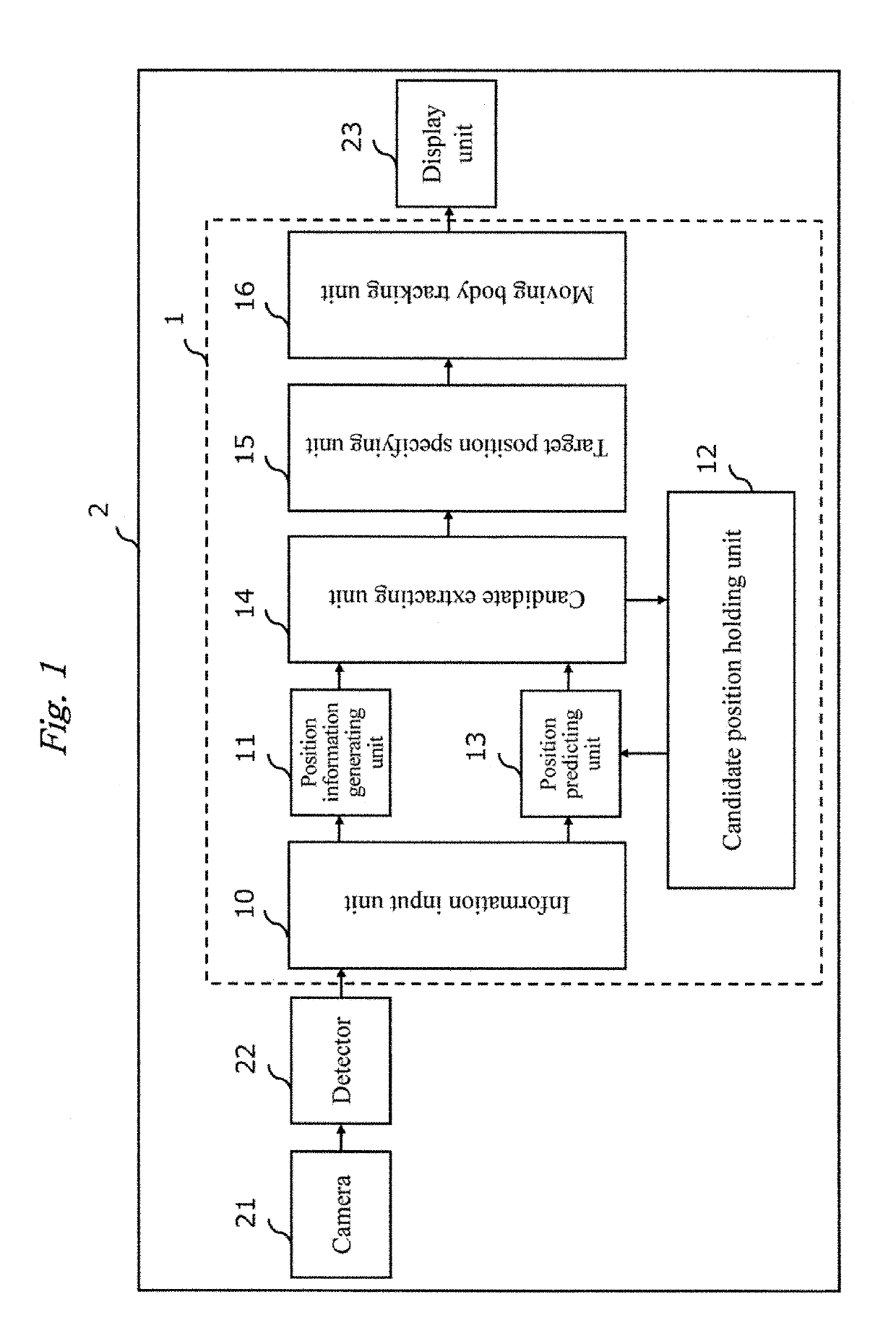
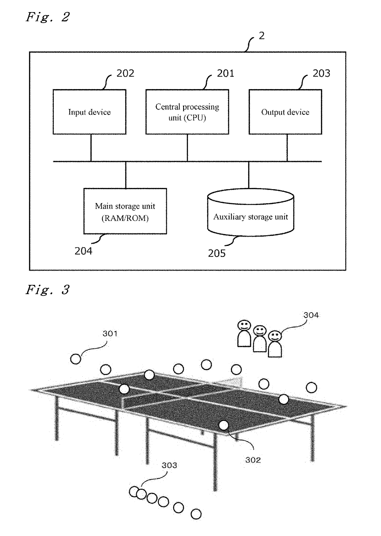
[0052]FIG. 1 shows a block diagram of a device 2 including a moving body tracking device 1. The device illustrated in FIG. 1, which may include an electric appliance such as a smart phone, a personal digital assistant, a digital camera, a game terminal, and a television, has a hardware configuration as illustrated in FIG. 2. As illustrate...
examples
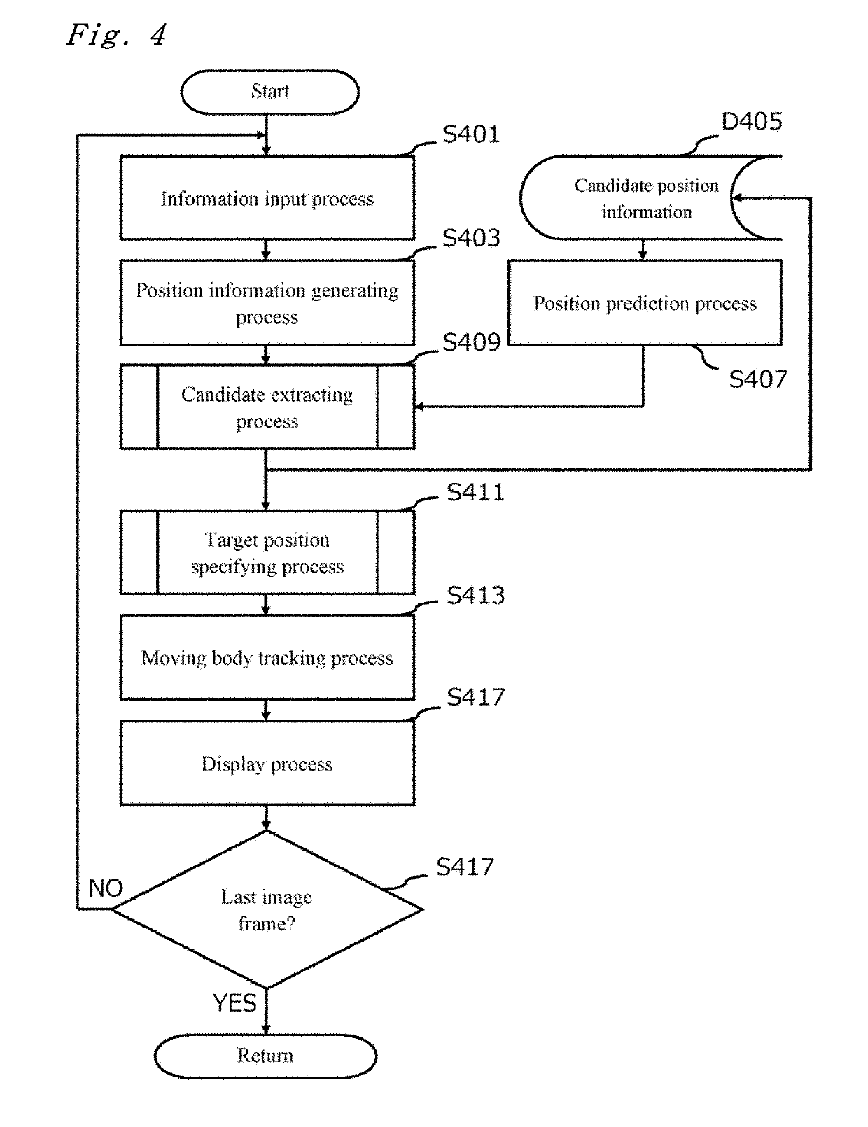
[0105]In the description for the operation of the moving body tracking device 1 according to this embodiment, considering ease of understanding of the description, as an example of the operation of the moving body tracking device according to an embodiment of the disclosure, the moving body tracking device that tracks the ball in the table tennis has been described. This is referred to as Example 1. In a way of comparing with Example 1, an example of ball tracking in the volleyball (Example 2), an example of ball tracking in pitching in the baseball (Example 3), and an example of ball tracking in the golf (Example 4) will be described.
[0106]In Example 1 and Example 2 to Example 4, the same configuration of the moving body tracking device 1 as illustrated in FIG. 1 according to this embodiment may be utilized, and the device 2 as illustrated in FIG. 2 may also be realized in a similar way. The contents of the processes are different since the conditions by the given environments are ...
embodiment 2
[0113]A moving body tracking device according to Embodiment 2 has a configuration illustrated in FIG. 1 identical to that of the moving body tracking device 1 according to Embodiment 1, and is also realized as the device 2 illustrated in FIG. 2 in a similar manner thereof. As for the function, the moving body tracking device 1 and the candidate extracting unit 14 of Embodiment 1 have different functions from those of Embodiment 2. Therefore, the candidate extracting unit will be mainly described, but the description overlapping that of Embodiment 1 will be omitted.
[0114]The candidate extracting unit 14 according to Embodiment 2 has a function of calculating the likelihood score from the position information of the candidate having been detected from the image data in the image frame (the second image frame) having been input from the position information generating unit 11 and the prediction position information in the same image frame (the second image frame) having been input from...
PUM
 Abstract
Description
Claims
Application Information
 - R&D
- Intellectual Property
- Life Sciences
- Materials
- Tech Scout
- Unparalleled Data Quality
- Higher Quality Content
- 60% Fewer Hallucinations
Browse by: Latest US Patents, China's latest patents, Technical Efficacy Thesaurus, Application Domain, Technology Topic, Popular Technical Reports.
© 2025 PatSnap. All rights reserved.Legal|Privacy policy|Modern Slavery Act Transparency Statement|Sitemap|About US| Contact US: help@patsnap.com


