
Implant-cinching devices and systems

a technology of implant clamping and elongation, applied in the field of implant clamping, can solve the problems of reducing cardiac output, increasing total stroke volume, and ultimate weakening of the left ventricle, and achieve the effect of facilitating sliding of the elongate member

Active Publication Date: 2019-05-02
VALTECH CARDIO LTD
View PDF0 Cites 58 Cited by
  • Summary
  • Abstract
  • Description
  • Claims
  • Application Information

AI Technical Summary

Benefits of technology

The patent describes a system for adjusting the size of a pouch by stretching it. The system includes a gripper that prevents the elongate member from coming back out of the pouch. This results in a reduction of the length of the elongate member that is exposed outside of the pouch. The technical effect of this system is its ability to securely hold and adjust the size of a pouch.

Problems solved by technology

Mitral regurgitation of blood from the left ventricle into the left atrium results in increased total stroke volume and decreased cardiac output, and ultimate weakening of the left ventricle secondary to a volume overload and a pressure overload of the left atrium.
Dilation of other regions of the heart, vascular system, and / or other valve annuluses can also result in similar problems, including regurgitation at other valves.

Method used


Image

  • Implant-cinching devices and systems
  • Implant-cinching devices and systems
  • Implant-cinching devices and systems

Examples


exemplary embodiment 80

[0138]FIG. 5 shows an exemplary embodiment 80 of gripper 40, which has a unidirectional state in which the gripper facilitates one-way sliding of portion 28 therethrough. Gripper 80 can comprise one or more wheels 82, each wheel comprising a gripping surface 84 (e.g., comprising a plurality of teeth or comprising other frictional element(s)) that can grip portion 28. Wheels 82 can be configured to rotate in only one rotational direction, and thereby facilitate movement of portion 28 in a first direction through the gripper into pouch 50, but not in a second direction through the gripper out of the pouch. For example, gripper 80 may comprise a pawl 86 that allows rotation of wheel 82 in only one rotational direction. Optionally, the one or more wheels could be configured to allow rotation in both directions until locked or secured to prevent further movement.

exemplary embodiment 100

[0139]FIGS. 6A and 6B show an exemplary embodiment 100 of gripper 40 in which the gripper has (i) an unlocked state in which it facilitates sliding of portion 28 in either direction therethrough, and (ii) a locked state in which it inhibits the sliding of the portion in either direction. Optionally, the gripper can be biased to assume the locked state.

[0140]For some applications, gripper 100 can comprise at least one locking element 102 (e.g., a jaw, latch, contact edge, etc.) that, in the locked state, clamps onto portion 28 or elongate member 26. The jaw 102 (or other locking element) can have a gripping surface 104, such as one or more teeth or other frictional feature(s), that frictionally engages or grips portion 28 when the locking element or jaw contacts or clamps onto the portion of elongate member 26.

[0141]The system can also comprise an unlocker 110, which can be configured to maintain the gripper in an unlocked state. Optionally, gripper 100 can be configured to automatic...


PUM


Abstract

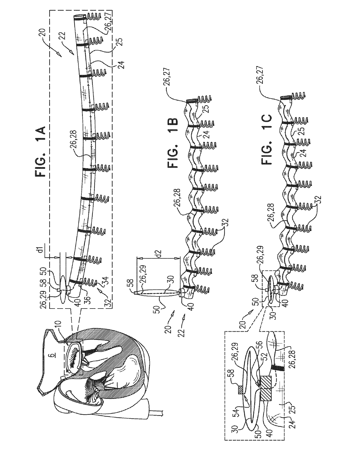
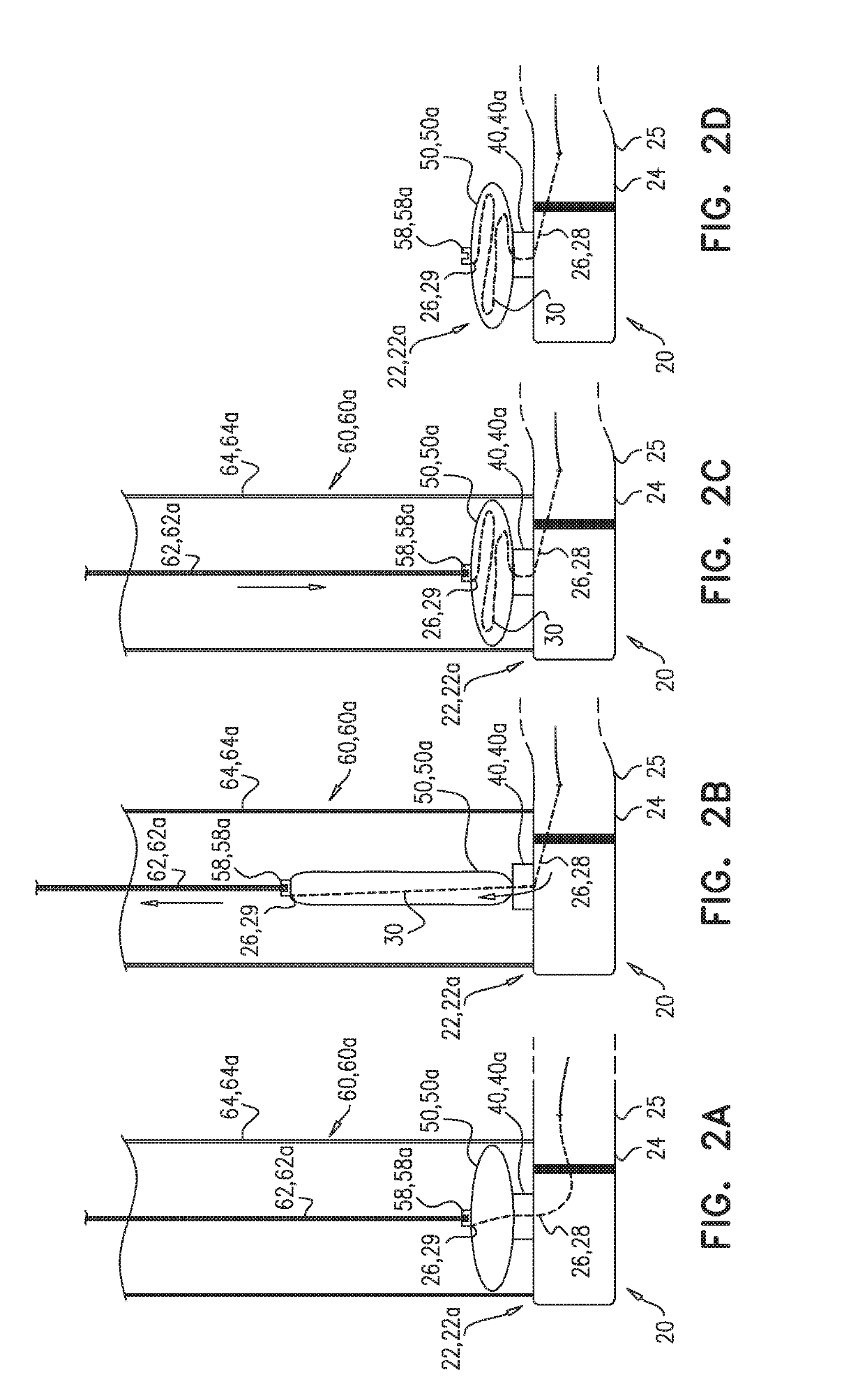
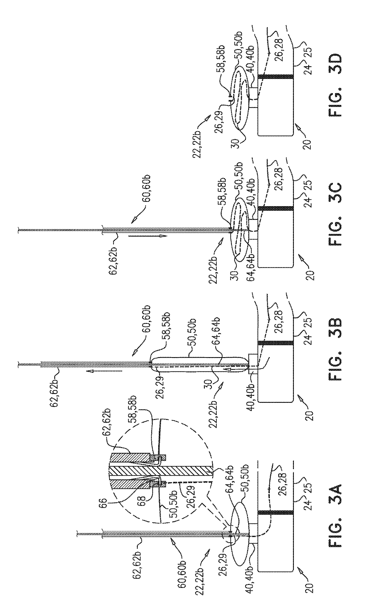
An implant having an implant body, a gripper, an elastic pouch, and an elongate member. The pouch can be coupled to the gripper, can have a first part and a second part, can have a contracted state toward which the pouch is elastically biased, and can be reversibly stretchable into a stretched state. The elongate member can have a first end portion coupled to the implant body, a second end portion fastened to the second part of the pouch, and a mid-portion extending (i) from the second end portion, through the pouch to the first part of the pouch, and (ii) out of the pouch to the first end portion. In at least one state of the gripper, the mid-portion can be slidable through the gripper and into the pouch. Other embodiments are also described.

Description

CROSS-REFERENCES TO RELATED APPLICATIONS[0001]The present application claims priority from U.S. Provisional application 62 / 580,646 to Sheps et al., filed Nov. 2, 2017, and entitled “Implant-cinching devices and systems,” which is incorporated herein by reference.FIELD OF THE INVENTION[0002]Some applications of the present invention relate in general to adjustment of an implant. For example, some applications of the present invention relate to contraction of a cardiovascular implant.BACKGROUND[0003]Ischemic heart disease can cause valve regurgitation, such as mitral regurgitation by the combination of ischemic dysfunction of the papillary muscles, and the dilatation of the left ventricle that is present in ischemic heart disease, with the displacement of the papillary muscles and the dilatation of the mitral valve annulus.[0004]Dilation of the annulus of the mitral valve (or another valve) can prevent the valve leaflets from fully coapting when the valve is closed. Mitral regurgitati...

Claims


Application Information

Patent Timeline
Patent Type & Authority Applications(United States)
IPC IPC(8): A61B17/00A61B17/12
CPCA61B17/00234A61B17/12013A61B17/0057A61B2017/00243A61F2210/0057A61F2/2445A61F2/2478A61F2220/0016A61F2250/0007A61F2250/001A61B2017/0649A61B17/068A61B2017/0496A61F2/9517A61F2/2466
Inventor SHEPS, TALKEIDAR, YARONZIPORY, YUVALCONKLIN, BRIAN S.
Owner VALTECH CARDIO LTD
Features
  • Generate Ideas
  • Intellectual Property
  • Life Sciences
  • Materials
  • Tech Scout
  • Unparalleled Data Quality
  • Higher Quality Content
  • 60% Fewer Hallucinations
Learn More