Life prediction apparatus

Active Publication Date: 2019-05-02
FANUC CORP
View PDF7 Cites 3 Cited by
  • Summary
  • Abstract
  • Description
  • Claims
  • Application Information

AI Technical Summary

Benefits of technology

[0009]The present invention eliminates the need for the structure of a detector or

Problems solved by technology

These cables become fatigued by being bent or twisted with operation of each joint of the robot.
With the progress of fatigue, a trouble such as a break occurs in a cable, which may lead to a halt of the robot.
On the other hand, as for life prediction of a cable wired in a robot, its life calculation method has not been established.
However, in the above-described prior art techniques of detecting an abnormality of the cable, a device for detecting a

Method used


Image

  • Life prediction apparatus
  • Life prediction apparatus
  • Life prediction apparatus

Examples


first embodiment

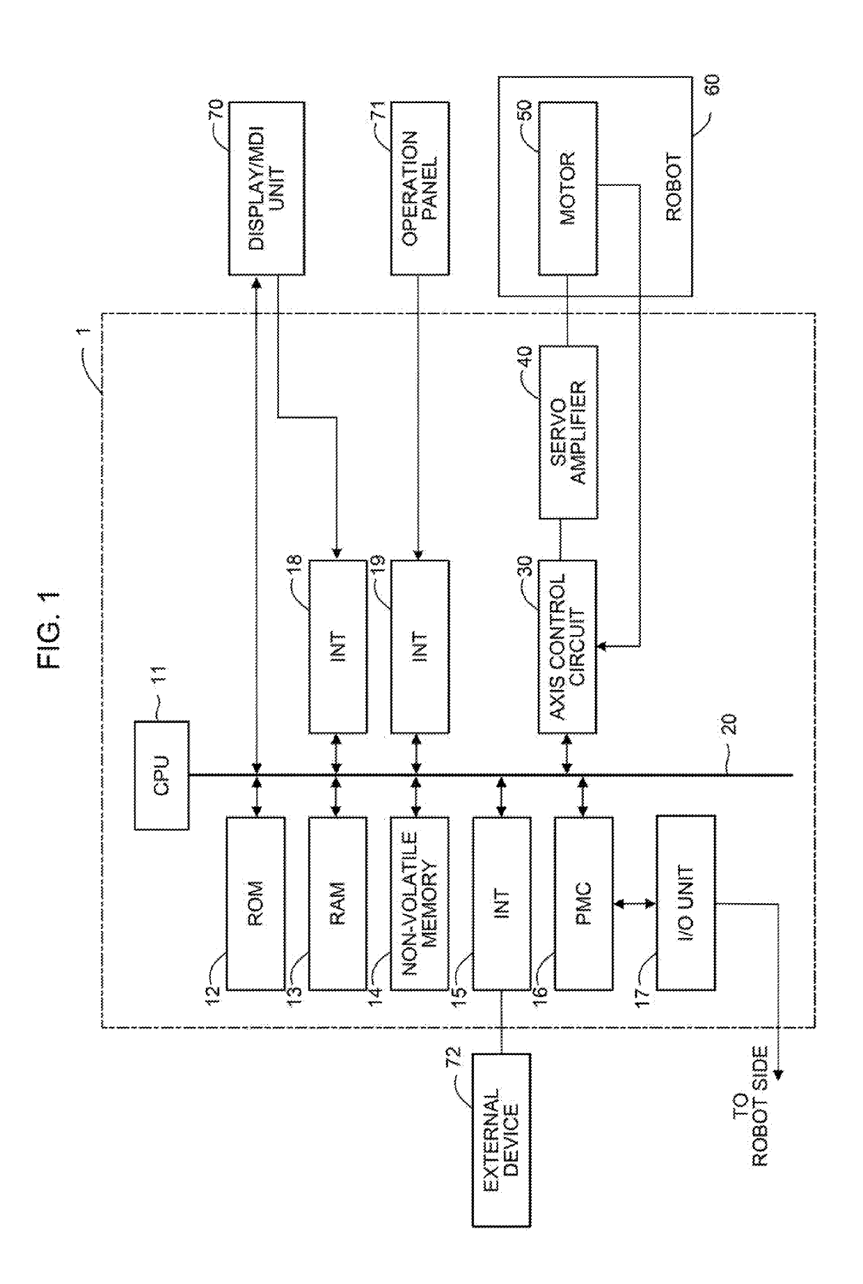
[0020]FIG. 1 is a schematic diagram of hardware structure of main parts of a life prediction apparatus according to the present invention. A life prediction apparatus 1 of the present invention can be implemented as, for example, a controller for a robot 60. The life prediction apparatus 1 of the present invention can also be implemented as, for example, a host computer, cell computer, cloud server, or the like connected to a controller of the robot 60 via a network or the like.

[0021]The life prediction apparatus 1 according to the present embodiment includes a CPU 11, which is a processor for generally controlling the life prediction apparatus 1. The CPU 11 reads a system program stored in a ROM 12 via a bus 20 to control the entire life prediction apparatus 1 in accordance with the system program. In a RAM 13, temporary computation data, display data, various data inputted by an operator via a display / MDI unit 70, which will be described further below, and so forth are stored.

[002...

second embodiment

[0042]FIG. 6 is a schematic diagram of hardware structure of main parts of a life prediction apparatus according to the present invention. The life prediction apparatus 1 of the present embodiment can be implemented as, for example, a host computer, cell computer, cloud server, or the like connected to controllers of a plurality of robots 60 of the same type via a network or the like. The basic function of each of the CPU 11, the ROM 12, the RAM 13, and the non-volatile memory 14, which are provided in the life prediction apparatus 1, is similar to that described with reference to FIG. 1.

[0043]The life prediction apparatus 1 according to the present embodiment has a function of receiving, via an interface 22, data collected from a controller of each robot 60 connected via a network and estimating the position weighting factor K1(θ) and the allowable value C of the cable based on the received data. The life prediction apparatus 1 includes a machine learning apparatus 300 which estima...


PUM


Abstract

A life prediction apparatus is configured to accurately predict a life of a cable wired at a joint part of a robot. The life prediction apparatus includes a fatigue-level estimation unit for estimating a fatigue level of the cable based on encoder information of an actuator which moves the joint part of the robot, and a life prediction unit for predicting the life of the cable based on a fatigue level of the cable estimated by the fatigue-level estimation unit and an allowable value of the cable.

Description

BACKGROUND OF THE INVENTION1. Field of the Invention[0001]The present invention relates to life prediction apparatuses and, in particular, to a life prediction apparatus which predicts the life of a cable wired at joint parts of a robot.2. Description of the Related Art[0002]In an articulated robot, as depicted in FIG. 8, it is required to wire a motor cable for moving each joint, a cable for driving a device attached to the robot, a signal cable to an encoder, and so forth over joint parts. These cables become fatigued by being bent or twisted with operation of each joint of the robot. With the progress of fatigue, a trouble such as a break occurs in a cable, which may lead to a halt of the robot. Therefore, it is important to predict the life of each cable and replace the cable at an appropriate time.[0003]For prediction of the life of a component such as a bearing, a speed reducer, or the like configuring a robot, Japanese Patent Application Laid-Open Nos. 2017-119320, 2013-14434...

Claims


Application Information

Patent Timeline
IPC IPC(8): G05B19/4065G01R31/02G05B23/02B25J19/06B25J13/06
CPCG05B19/4065G01R31/021G05B23/0283B25J19/06B25J13/06G05B13/048G05B2219/37254B25J9/1674B25J19/0095B25J19/0025G01R31/58
Inventor TANNO, YOSHIHIROOIKAWA, AKIHIROOHASHI, TOSHINORI
Owner FANUC CORP
Why Eureka
Try Eureka