Laparoscopic device

a laparoscopic and device technology, applied in the field of laparoscopic devices, can solve the problems of difficult suturing tissues together using a regular laparoscopic instrument, loss of dexterity, and limited range of motion of surgeons,

Active Publication Date: 2019-05-16
LAPROTECH
View PDF4 Cites 1 Cited by
  • Summary
  • Abstract
  • Description
  • Claims
  • Application Information

AI Technical Summary

Benefits of technology

[0022]Viewed from a second perspective, the present teachings can provide a laparoscopic device wherein the user is able to manipulate the attached tool member without the need for additional instruments such as e.g. forceps. The laparoscopic device as described herein can be used when there is a need to use a suturing needle having a fixed angle at the surgical site. In a further embodiment this may be achieved by a laparoscopic device comprising a handle assembly by which the user may hold the laparoscopic device, and a tool gripping assembly which holds one or more tool members. The tool gripping assembly comprises a longitudinally extending rod having a longitudinal axis A, a distal end and a proximal end. The proximal end is configured to be attached to the handle assembly and the distal end is provided with one or more holding members capable of holding the one or more tool members. The tool gripping assembly further comprises a sleeve partially surrounding and being longitudinally and independently displaceable parallel...

Problems solved by technology

Although laparoscopic surgery provides many advantages one of the disadvantages is that sometimes the surgeon has limited range of motion due to limited space at the surgical site, which results in a loss of dexterity.
Under certain circumstances the available space at the surgical site is so restricted that suturing tissues together usi...

Method used


Image

  • Laparoscopic device
  • Laparoscopic device
  • Laparoscopic device

Examples


Embodiment Construction

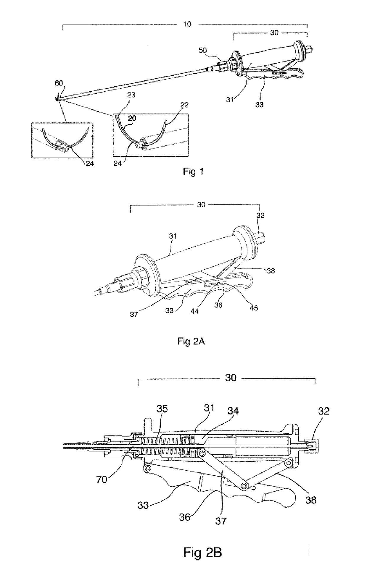
[0066]FIG. 1 is a view of the laparoscopic device 10 holding a tool member 20. The laparoscopic device 10 comprises a handle assembly 30 by which the user may hold the device 10, a tool angle adjusting assembly 50, and a tool gripping assembly 60 which grips a tool member 20. In the illustrated embodiments the tool member 20 is a curved or straight suturing needle. However, it is also contemplated that the tool member 20 may be forceps, scissors, probes, dissectors, hooks or retractors. In some embodiments the laparoscopic device 10 may also be used for gripping and handling suture threads.

[0067]The handle assembly 30 comprises a housing 31 and an actuation lever 33 (FIGS. 2A, 2B). The handle assembly 30 is designed to be held by one hand (left or right) by gripping around the housing 31 and the actuation lever 33. The housing 31 comprises a slider 34 and a spring 35 (FIG. 2B) and the actuation lever 33 can be provided with a finger grip 36 to enable safe and precision handling of t...


PUM


Abstract

A laparoscopic device (10) comprising a handle assembly (30) by which the user may hold the laparoscopic device (30); and a tool gripping assembly (60) which holds a tool member (20) is disclosed. The tool gripping assembly (60) comprises a longitudinally extending rod (70) having a longitudinal axis A, a distal end (71) and a proximal end (72) The proximal end (72) is configured to be attached to the handle assembly (30), said distal end (71) is provided with a holding member (73) capable of holding a tool member (20). The tool gripping assembly (60) further comprises a first sleeve (80) partially surrounding and being longitudinally and independently displaceable parallel to the longitudinal axis A along an outer surface of said longitudinally extending rod (70), and a second sleeve (90) partially surrounding and being longitudinally and independently displaceable parallel to the longitudinal axis A along an outer surface of said first sleeve (80). The first and second sleeves (80, 90) are longitudinally displaceable in relation to each other and said longitudinally extending rod (70), and are configured to clamp said tool member (20) to said holding member (73) in a variable angle α in relation to said longitudinal axis A, wherein said variable angle α depends on the relative positions of the first and second sleeves (80, 90) to the longitudinally extending rod (70).

Description

TECHNICAL FIELD[0001]The present application relates to a laparoscopic device which enables a tool member held therewith to be used at fixed or variable angles during surgical procedures.BACKGROUND OF THE INVENTION[0002]During laparoscopic surgery operations are performed far from their location through small incisions (usually 0.5-1.5 cm) elsewhere in the body. There are a number of advantages to the patient with laparoscopic surgery versus the more common, open procedure. Pain and hemorrhaging are reduced due to smaller incisions and recovery times are shorter.[0003]During laparoscopic surgery the key element is the use of a laparoscope, a long fiber optic cable system which allows viewing of the affected area by snaking the cable from a more distant, but more easily accessible location. As the surgery is performed at a distance, instruments with long handles are used in order to perform all steps of the operation. In laparoscopic procedures a plurality of tubular members e.g. tro...

Claims


Application Information

Patent Timeline
IPC IPC(8): A61B17/04A61B17/062
CPCA61B17/0469A61B17/062A61B2017/06057A61B2017/2919A61B2017/2944A61B17/29A61B2017/00473A61B2017/2912A61B2017/2927A61B17/0487A61B17/00234A61B2017/00349
Inventor NAJAR, AZAD
Owner LAPROTECH
Why Eureka
Try Eureka