Filter element

a filter element and filter element technology, applied in the field of filter elements, can solve the problems of limiting the amount of usable space available in the fluid system, and reducing the service life of the filter element, so as to minimize the danger of undeired electrostatic discharge

Active Publication Date: 2019-05-16
FILTERTECHN
View PDF3 Cites 1 Cited by
  • Summary
  • Abstract
  • Description
  • Claims
  • Application Information

AI Technical Summary

Benefits of technology

[0011]Against this background, an object of the invention is to provide an improved filter element and a hydraulic circuit having such a filter element, in which, given a cost-effective and functionally reliable design, the danger of undesired electrostatic discharge is minimized.
[0012]This object is basically achieved by a filter element and a hydraulic circuit having such filter element where the filter element has a greater effective filtering surface available due to an alternating sequence of filter pleats having a first pleat height and of filter pleats having a second pleat height, than is the case with known solutions with filter pleats having a uniform pleat height. To a person of average skill in the field of filtration technology, surprisingly such configuration of filter pleats and a corresponding flow-through of a fluid to be filtered results in an overall lower surface load to the filter medium, and in a lower velocity at which the fluid passes during filtration, which, in turn, assists in significantly reducing the static charge of the filter medium during operation of the filter.
[0013]A stabilization takes place as a result of the aforementioned configuration of filter pleats, wherein the filter pleats of the second pleat height reinforce the filter pleats of the first pleat height. Thus, a pressure-resistant and functionally reliable structure for the filter medium is achieved via the filter pleats of the differing height characteristic. In addition, the filter pleats of the first pleat height are maintained in their original configuration during operation of the filter element and, in this way, have a particularly large effective filtering surface facing the dirt side or the clean side. The open surface facing the dirty side or the clean side is therefore larger than in the case of conventional filter elements having a uniform pleat height over the entire circumference, which are routinely prone to the aforementioned “blocking”. Hence, this structure allows the fluid in the solution according to the invention to more easily penetrate the filter medium, which results in a filter element having improved filter efficiency over the life of the filter, and having a longer service life.
[0014]Efforts are frequently made in filtration technology to optimize the filter element with its filter medium such that a high flow-through efficiency, in addition to a high cleaning efficiency, is achieved by using as many individual filter pleats of the same insertion height as possible in the element. Here, a different approach is taken by simply dispensing with a plurality of individual pleats of the same height and, therefore, with theoretically available filtering surface. By reducing the height of the filter pleats having the second pleat height, the lateral boundary surfaces of the adjoining filter pleats of the first filter height are kept free for a flow-through. In this way, those surfaces increase the effective filtering surface and, therefore, the flow-through efficiency and the separating efficiency of the filter medium. A lower flow-through velocity for the fluid has been shown to be achieved as a result of the associated, on the whole lower, surface load to the filter medium with a comparable flow-through efficiency, as compared to known solutions. The result is that electrostatic charges do not even occur or occur at least only to a reduced extent, so that the charges need not be overcome via additional structural measures, such as a contact device or a selective choice of filter materials having different potentials.
[0019]In addition, straight or planar sections of the filter pleats may each be spaced apart from one another. This spacing ensures that the fluid present on the dirt side is present over the entire surface of the filter medium at an approximately uniform pressure. Thus, the entire surface of the filter medium bears approximately the same surface load. In particular, this structure avoids turbulences during the flow-through of the filter medium, which otherwise promote the electrostatic charge.
[0020]In one particularly advantageous embodiment, the pleated filter medium has a tubular design, and the straight or planar sections of the filter pleats each extend in a plane, in which a central longitudinal axis of the filter element is also situated. This configuration yields a particularly high packing density of the filter medium with a plurality of filter pleats of varying pleat heights.

Problems solved by technology

In many cases, only a limited amount of usable space is available in fluid systems, in which the filter elements are used, for installing or removing system parts that contain the relevant filter cartridge-type filters.
This displacement results in a type of “blocking” of the element material in this contiguous region, since the medium to be filtered is then no longer able to reach uninterruptedly all the filter folds of the element structure.
Since the multilayer filter medium is routinely formed from individual nonwoven filter medium of individual fibers, this load increase results in an increased discharge of fiber material from the fleece-composite material (migration), which, in turn, reduces the service life of the filter element.
One great challenge the filtration technology must now face is the fact that, due to environmental regulations, the hydraulic fluids to be cleaned using primarily such filter elements may no longer include any metal additives, in particular, any environmentally harmful zinc additives.
Due to this reduced conductivity, electrostatic charges, as they routinely occur during flow-through of the medium, can no longer be effectively dissipated via the hydraulic fluid, as in the past.
As a result of this inability, discharge processes may occur in the filter element and may occur in the form of discharge flashes.
Those flashes routinely destroy the sensitive filter medium in the same way that they promote the oil aging of the hydraulic fluid(s).
Particularly in the case of in-tank applications of the filter element, in which the filter element is used in closed tank units, such discharge flashes may increase the danger of explosion.
However, maintaining the upstream contact device requires increased material and manufacturing expenditure, which, accordingly, reflects negatively in terms of the manufacturing costs of the element.
Nevertheless, here too, when selecting the filter insert materials in question, based on the aforementioned tribological voltage series, a correspondingly high expense must be incurred, both from the standpoint of pre-development as well as from the standpoint of material supply, to obtain positive results, which again increases the manufacturing costs of the filter element.
In addition, all of the known solutions described above have in common the fact that the disadvantageous “blocking” effect may occur as a result of displacement of free filter fold ends due to the flow-through of the fluid.

Method used


Image

  • Filter element
  • Filter element

Examples


Embodiment Construction

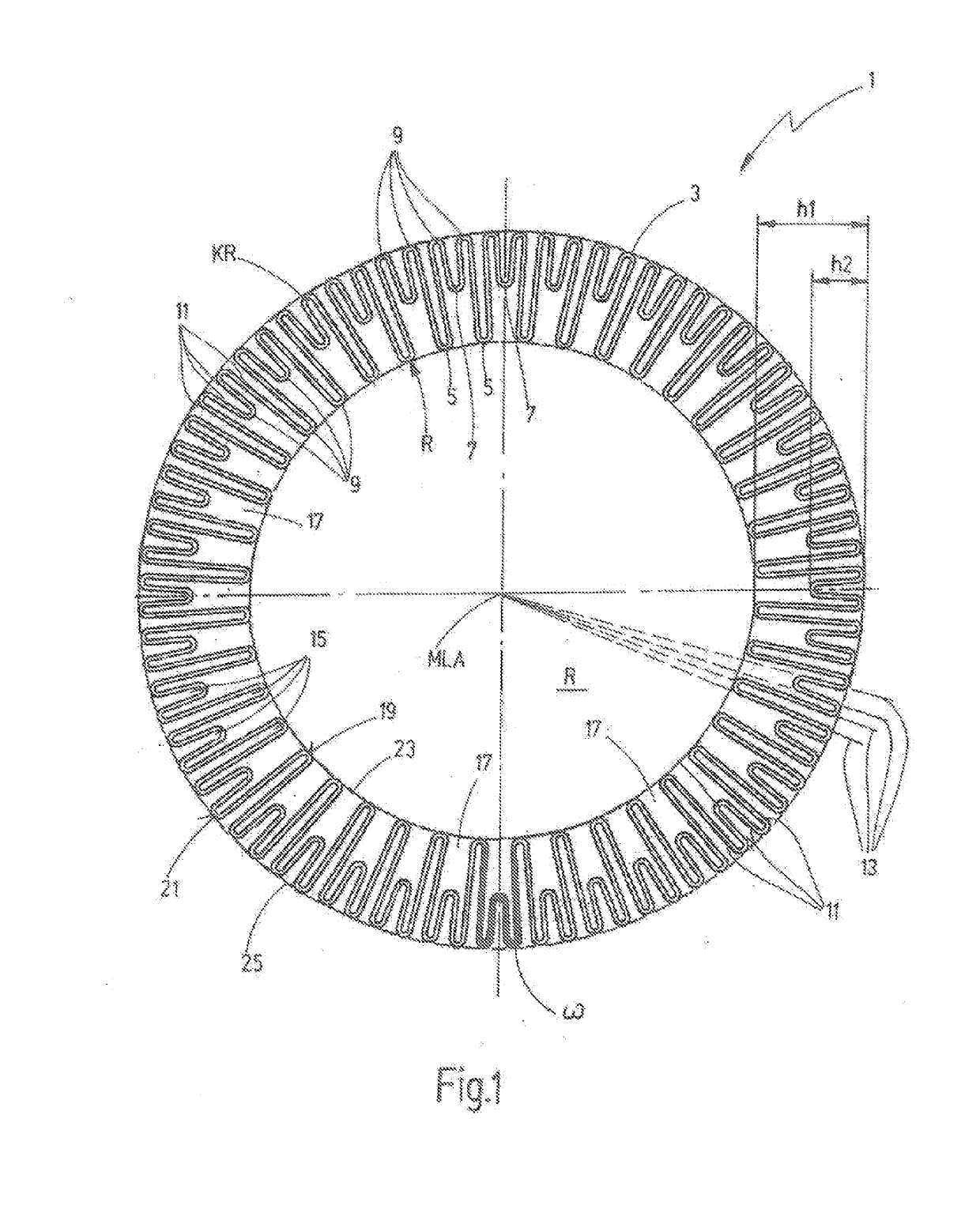
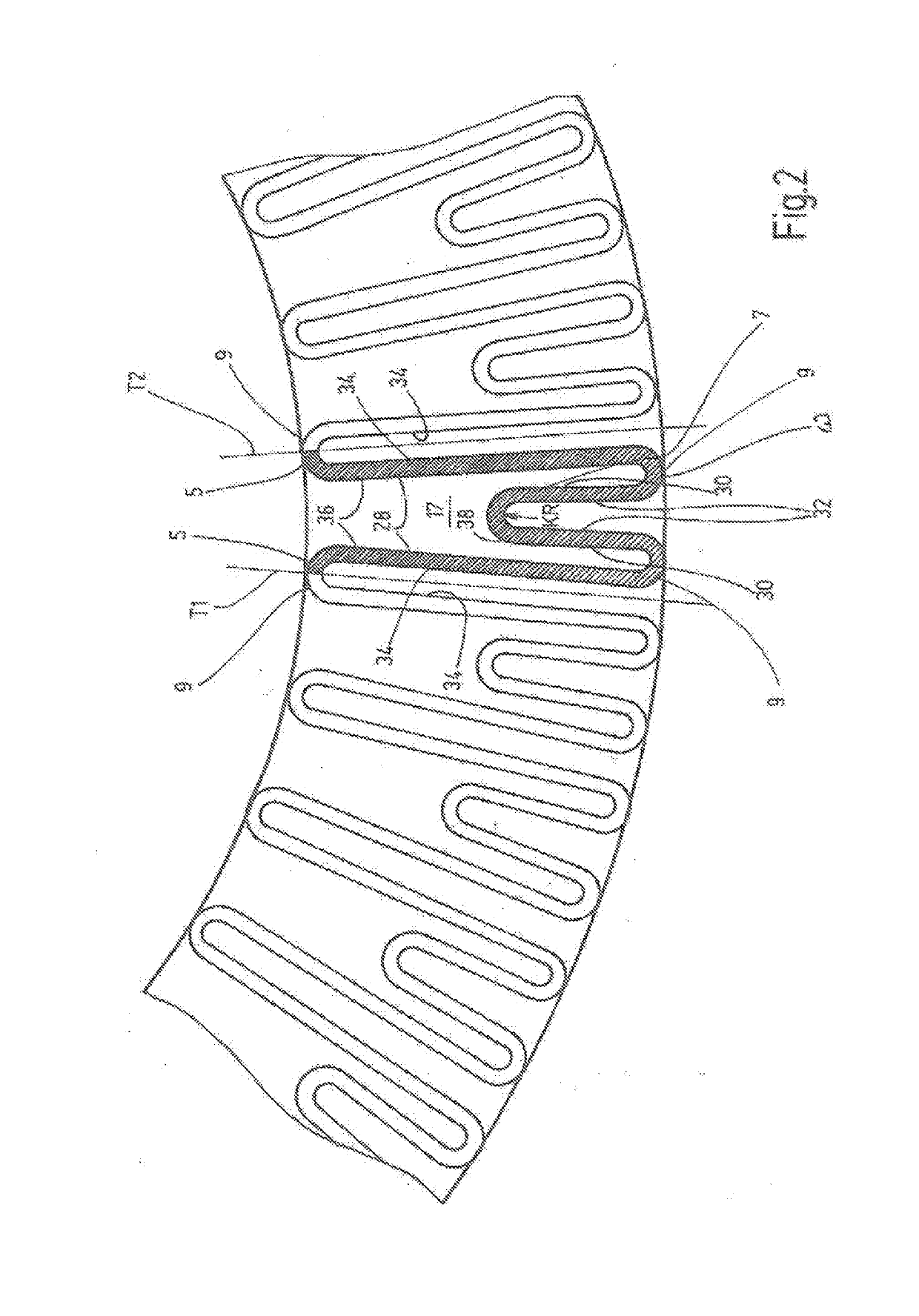
[0030]For the sake of simplicity, the filter element is depicted wholly or in part in FIGS. 1 and 2, in each case only in a front-end top view. The filter element as such routinely has a cylindrical shape, as is shown, for example, in the previously cited prior art documents DE 10 2004 005 202 A1 and WO 2009 / 089891 A1. In this respect, in terms of the overall configuration of the filter element, reference is made to the relevant documents.

[0031]FIG. 1 also shows a filter element 1 including a filter medium 3 having a multilayer structure. The filter medium 3 includes first and second filter pleats 5, 7 of varying first and second pleat heights h1, h2, respectively. The filter pleats have a sequence of first filter pleats 5 having a first pleat height hi alternating with second filter pleats 7 having a second pleat height h2. In this way, more effective filtering surface is available than in the case of filter elements, in which the filter pleats have a uniform pleat height. Upon flo...


PUM

PropertyMeasurementUnit
heightaaaaaaaaaa
lengthaaaaaaaaaa
curvature radiiaaaaaaaaaa

Abstract

A filter element has a preferably multilayer structure of a pleated filter medium (3) with a plurality of individual filter pleats (5, 7). Due to an alternating sequence of filter pleats (5) with a first pleat height (h1) and filter pleats (7) with a second pleat height (h2), more effective filter surfaces are available than with filter pleats with a uniform pleat height. Upon throughflow by a fluid to be filtered, a lower surface load for the filter medium (30 and lower passage speed of the fluid are present during filtration. A static loading of the filter medium (3) during operation of the filter is then reduced. A hydraulic circuit has such a filter element (1).

Description

REFERENCE TO RELATED APPLICATION[0001]This application is a continuation of U.S. patent application Ser. No. 14 / 440,665, filed May 5, 2015 and entitled “Filter Element and Hydraulic Circuit with Such Filter Element,” the entire subject matter of which is hereby incorporated by reference.FIELD OF THE INVENTION[0002]The invention relates to a filter element with a pleated filter medium having a preferably multilayer structure, including a plurality of individual filter pleats. In addition, the invention relates to a hydraulic circuit of such a filter element.BACKGROUND OF THE INVENTION[0003]Filter elements of this kind are available commercially. Such filter elements are widely used in conjunction with a variety of fluid systems for filtering process fluids, pressure fluids such as hydraulic oil, as well as liquid fuels and lubricants for preparing fluid media and the like.[0004]In many cases, only a limited amount of usable space is available in fluid systems, in which the filter ele...

Claims


Application Information

Patent Timeline
Patent Type & Authority Applications(United States)
IPC IPC(8): B01D29/21B01D29/56B01D29/33
CPCB01D29/21B01D29/56B01D29/333B01D2201/122
Inventor OBERLI, FRANKSCHOENFELD, DIRK
Owner FILTERTECHN
Why Eureka
Try Eureka