Method and system for detecting a mass imbalance in a wind turbine rotor

a wind turbine and rotor technology, applied in the field of wind turbines, can solve the problems of increasing the side-to-side bending moment of the tower, accelerating wear of the wind turbine, and high fatigue load, and achieve the effect of reducing the effect of mass imbalan

Active Publication Date: 2019-05-16
GENERAL ELECTRIC CO
View PDF17 Cites 7 Cited by
  • Summary
  • Abstract
  • Description
  • Claims
  • Application Information

AI Technical Summary

Benefits of technology

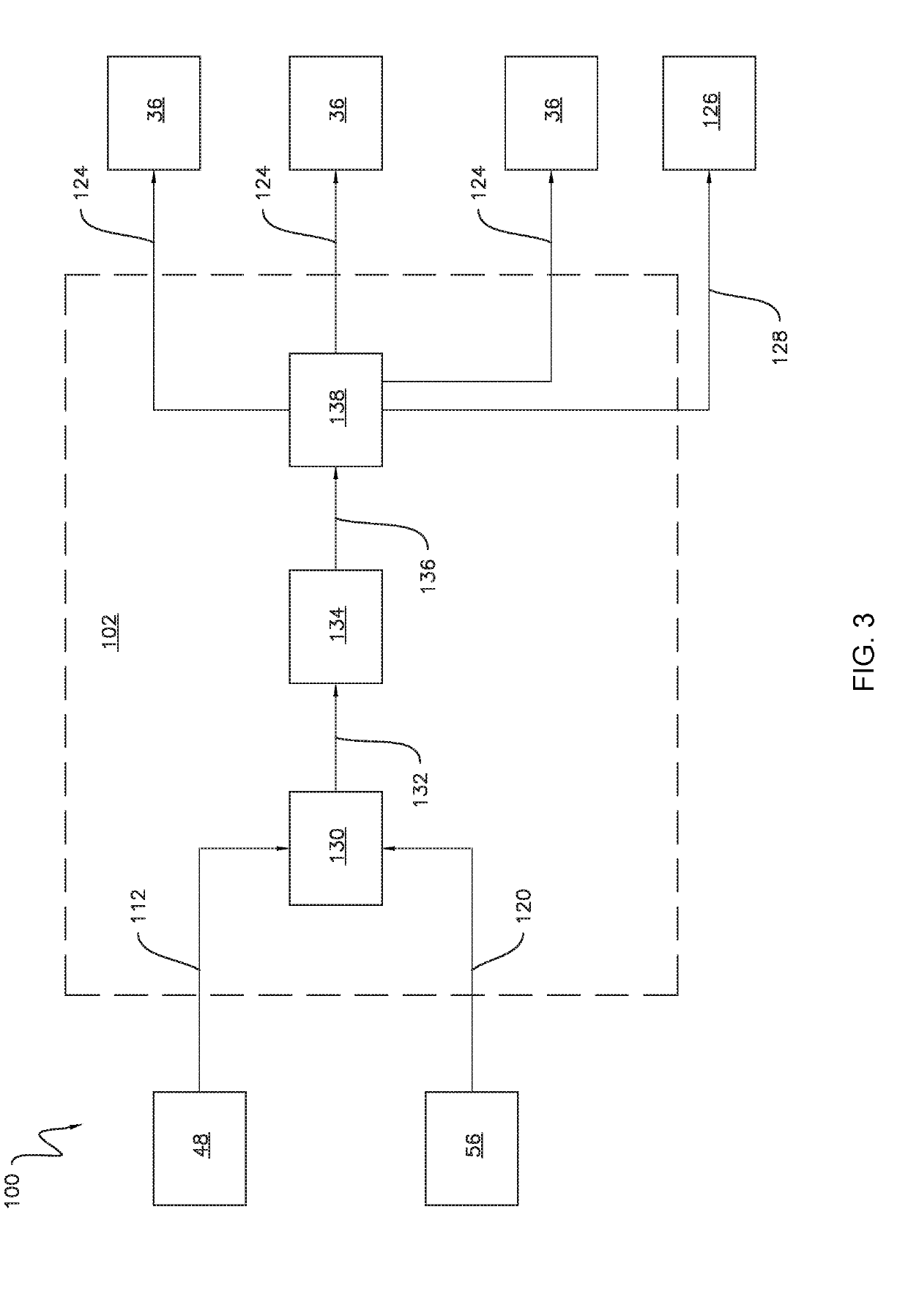
[0007]In another aspect, the present disclosure is directed to a system for detecting a mass imbalance in a rotor of a wind turbine. The system includes a rotor of the wind turbine with the rotor having one or more rotor blades. The system also includes a drivetrain of the wind turbine with the drivetrain being coupled to the rotor. Furthermore, the system includes a generator of the wind turbine with the generator being coupled to the drivetrain. Additionally, the system includes a sensor in operative association with the wind turbine. The sensor is configured to detect a parameter indicative of an operating characteristic of the wind turbine. Moreover, the system includes a controller communicatively coupled to the sensor. The controller being configured to determine a mean amplitude of a designated frequency component of the operating characteristic based on sensor measurements received from the sensor. The controller is also configured to determine when a mass imbalance is present within the rotor based on the mean amplitude of the designated frequency component. Furthermore, the system is configured to, when the mass imbalance is present within the rotor, initiate a control action associated with reducing an effect of the mass imbalance on the wind turbine.

Problems solved by technology

In general, when a large mass imbalance is present in the rotor, the wind turbine may experience accelerated wear.
For example, large mass imbalances may result in high fatigue loads and increased side-to-side bending moments within the tower as well as large torque cycling within the drivetrain.
As such, large mass imbalances may reduce the life of the various components of the wind turbine, such as the tower and / or the drivetrain.
Furthermore, the mass imbalances may be amplified as the height of the tower increases and / or the stiffness of the tower decreases.

Method used


Image

  • Method and system for detecting a mass imbalance in a wind turbine rotor
  • Method and system for detecting a mass imbalance in a wind turbine rotor
  • Method and system for detecting a mass imbalance in a wind turbine rotor

Examples


Embodiment Construction

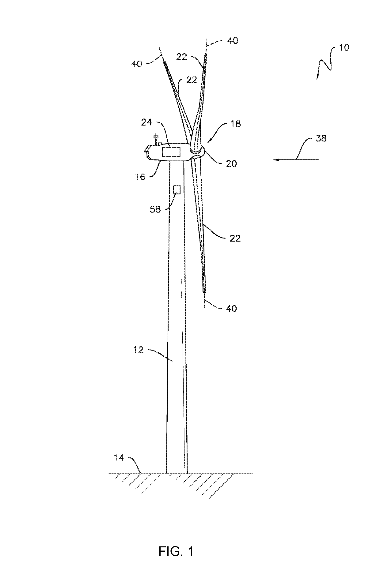
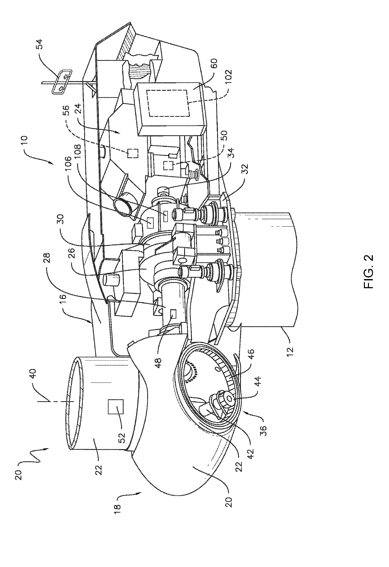
[0018]Reference will now be made in detail to present embodiments of the technology, one or more examples of which are illustrated in the accompanying drawings. The detailed description uses numerical and letter designations to refer to features in the drawings. Like or similar designations in the drawings and description have been used to refer to like or similar parts of the technology. As used herein, the terms “first”, “second”, and “third” may be used interchangeably to distinguish one component from another and are not intended to signify location or importance of the individual components.

[0019]Each example is provided by way of explanation of the technology, not limitation of the technology. In fact, it will be apparent to those skilled in the art that modifications and variations can be made in the present technology without departing from the scope or spirit thereof. For instance, features illustrated or described as part of one embodiment may be used on another embodiment...


PUM


Abstract

The present disclosure is directed to a method for detecting a mass imbalance in a rotor of a wind turbine. The method includes receiving, with a computing device, sensor data indicative of an operating characteristic of the wind turbine. The method also includes determining, with the computing device, a mean amplitude of a designated frequency component of the operating characteristic. Furthermore, the method includes determining, with the computing device, when a mass imbalance is present within the rotor based on the mean amplitude of the designated frequency component.

Description

FIELD[0001]The present disclosure generally relates to wind turbines. More particularly, the present disclosure relates methods and systems for detecting a mass imbalance in a rotor of a wind turbine.BACKGROUND[0002]Wind power is considered one of the cleanest, most environmentally friendly energy sources presently available, and wind turbines have gained increased attention in this regard. A modern wind turbine typically includes a tower, a nacelle mounted on the tower, a generator positioned in the nacelle, and a rotor having one or more rotor blades. The one or more rotor blades convert kinetic energy of wind into mechanical energy using known airfoil principles. A drivetrain transmits the mechanical energy from the rotor blades to the generator. The generator then converts the mechanical energy to electrical energy that may be supplied to a utility grid.[0003]In general, when a large mass imbalance is present in the rotor, the wind turbine may experience accelerated wear. For ex...

Claims


Application Information

Patent Timeline
Patent Type & Authority Applications(United States)
IPC IPC(8): F03D13/35F03D17/00G01H1/00
CPCF03D13/35F03D17/00G01H1/006F05B2270/334F05B2270/807F05B2270/328F03D7/0296F05B2260/966F05B2270/326F05B2270/335Y02E10/72
Inventor GBADAMASSI, OLADODJA ACHRAFAMBEKAR, AKSHAY KRISHNAMURTYGEORG, SOEREN
Owner GENERAL ELECTRIC CO
Why Eureka
Try Eureka