An expandable tube for deployment within a blood vessel

A technology for expanding tubes and blood vessels, applied in the field of expandable tubes, to achieve the effects of preventing blockage, reducing hospital stay, and high radial strength

Active Publication Date: 2020-01-14
OXFORD ENDOVASCULAR LTD
View PDF16 Cites 0 Cited by
  • Summary
  • Abstract
  • Description
  • Claims
  • Application Information

AI Technical Summary

Problems solved by technology

However, it is difficult to manufacture a tube with optimal characteristics for this application

Method used


Image

  • An expandable tube for deployment within a blood vessel
  • An expandable tube for deployment within a blood vessel
  • An expandable tube for deployment within a blood vessel

Examples


Embodiment Construction

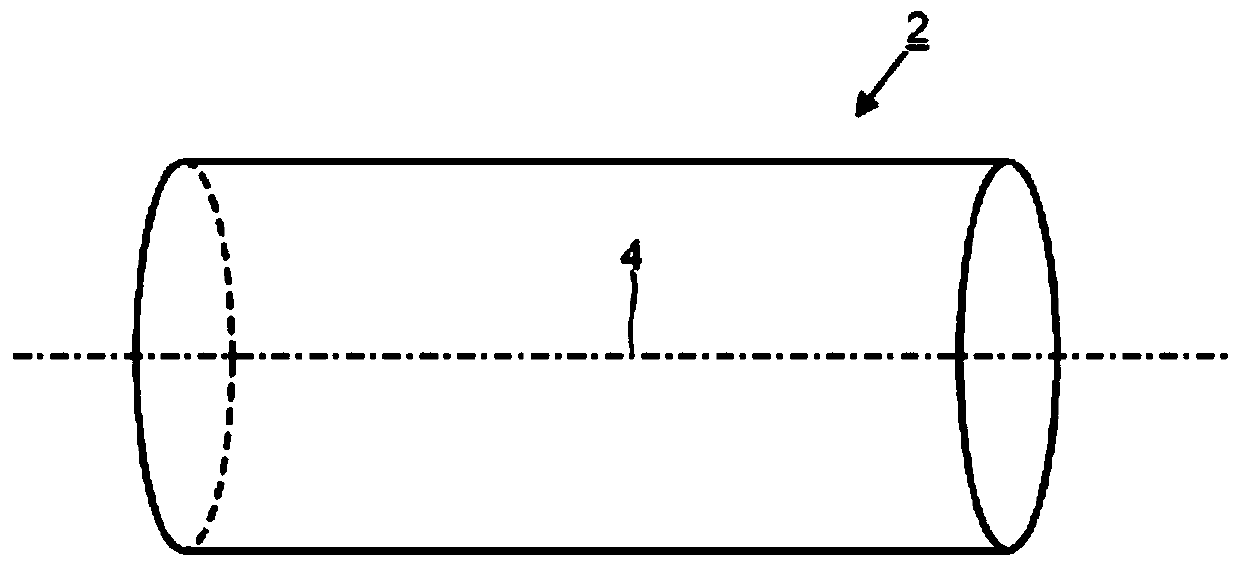
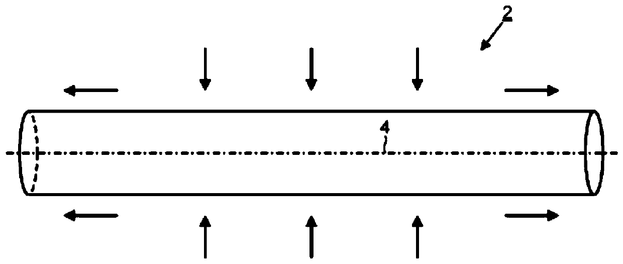
[0022] Embodiments of the invention provide a tube suitable for deployment within a blood vessel. The tube comprises an elongated frame 2 . figure 1 The external geometry of the frame 2 is shown in radially expanded and longitudinally contracted states. figure 2 The external geometry of the frame 2 is shown in radially contracted and longitudinally expanded states. Framework 2 can be accessed from figure 1 The radially expanded and longitudinally contracted states shown are reversibly switched to figure 2 The radially contracted and longitudinally expanded states are shown.

[0023] The frame 2 is expandable, optionally self-expanding. Frame 2 may comprise a shape memory alloy, such as Nitinol. Alternatively, frame 2 may comprise stainless steel, polymer or other biocompatible material.

[0024] The frame 2 is elongated relative to the extension axis 4 . For example, frame 2 may be cylindrical. When the frame 2 is cylindrical, the maximum transverse dimension is the ...


PUM


Abstract

An expandabletube for deployment within a blood vessel is disclosed. In one arrangement, the tube comprises an elongate frame that is reversibly switchable from a radially expanded and longitudinallycontracted state to a radially contracted and longitudinally expanded state. The frame comprises a plurality of longitudinally deformable elements for providing longitudinal expansion and contractionof the frame and a plurality of circumferentially deformable elements for providing radial expansion and contraction of the frame. Thelongitudinally deformable elements can be expanded or contracted longitudinally substantially without any change in the shape of the circumferentially deformable elements. The plurality of circumferentially deformable elements comprises a plurality of sets of circumferentially deformable elements. Eachset of circumferentially deformable elements forms a closed ring around an axis of elongation of the frame. Each closed ring consisting exclusively of the circumferentially deformable elements. At least two of the closed rings occupy overlapping ranges of longitudinal positions when the frame is in the radially expanded and longitudinally contracted state and occupy non-overlapping ranges of longitudinal positions when the frame is in the radially contracted and longitudinally expanded state.

Description

technical field [0001] The present invention relates to an expandable tube for deployment within a blood vessel, in particular an expandable tube for redirecting blood flow away from the aneurysm sac. Background technique [0002] An intracranial aneurysm is a region of weakness in the wall of an artery in the brain where dilation or bulging of the artery wall may occur. Histologically, reductions in the media, the middle muscular layer of the artery, and the internal elastic lamina lead to structural defects. These defects, combined with hemodynamic factors, lead to the outward bulging of the aneurysm. Intracranial aneurysms are a fairly common condition, affecting between one and five percent of adults, according to autopsy studies. In the United States alone, 10 to 12 million people suffer from intracranial aneurysms. [0003] Current methods for treating intracranial aneurysms include surgical clipping and endovascular coiling. In the craniotomy clipping approach, th...

Claims


Application Information

Patent Timeline
Patent Type & Authority Applications(China)
IPC IPC(8): A61F2/915
CPCA61F2/915A61F2002/91575A61F2230/0054A61F2002/823
Inventor 邓肯·基布尔
Owner OXFORD ENDOVASCULAR LTD
Why Eureka
Try Eureka