Eureka AIR delivers breakthrough ideas for toughest innovation challenges, trusted by R&D personnel around the world.

Main stop valve

Active Publication Date: 2019-05-16
ELLIOTT EBARA TURBOMACHINERY CORP
View PDF0 Cites 0 Cited by
  • Summary
  • Abstract
  • Description
  • Claims
  • Application Information

AI Technical Summary

Benefits of technology

This patent describes a configuration that makes it easier to operate a valve by using a handle. The pilot sleeve is designed to move when the handle is operated, which reduces the force required to operate the valve compared to directly moving the valve rod. Additionally, the sliding ring on the valve rod can be stabilized by moving it in a specific range when the valve is vibrating. These technical features improve the user experience when using the valve.

Problems solved by technology

However, in the case of Patent Document 1, as indicated in Patent Document 2, the bypass flow path and the spring support sleeve make the structure of the T&T valve complicated.
Also, in Patent Document 2, the structure of the T&T valve including a pilot relay valve is still complicated because the pilot relay valve is embedded in the oil supply and drainage paths of the main body of the T&T valve.

Method used


Image

  • Main stop valve
  • Main stop valve
  • Main stop valve

Examples


Embodiment Construction

[0024]Hereinafter, a preferred embodiment of the present disclosure will be described in detail with reference to the accompanying drawings.

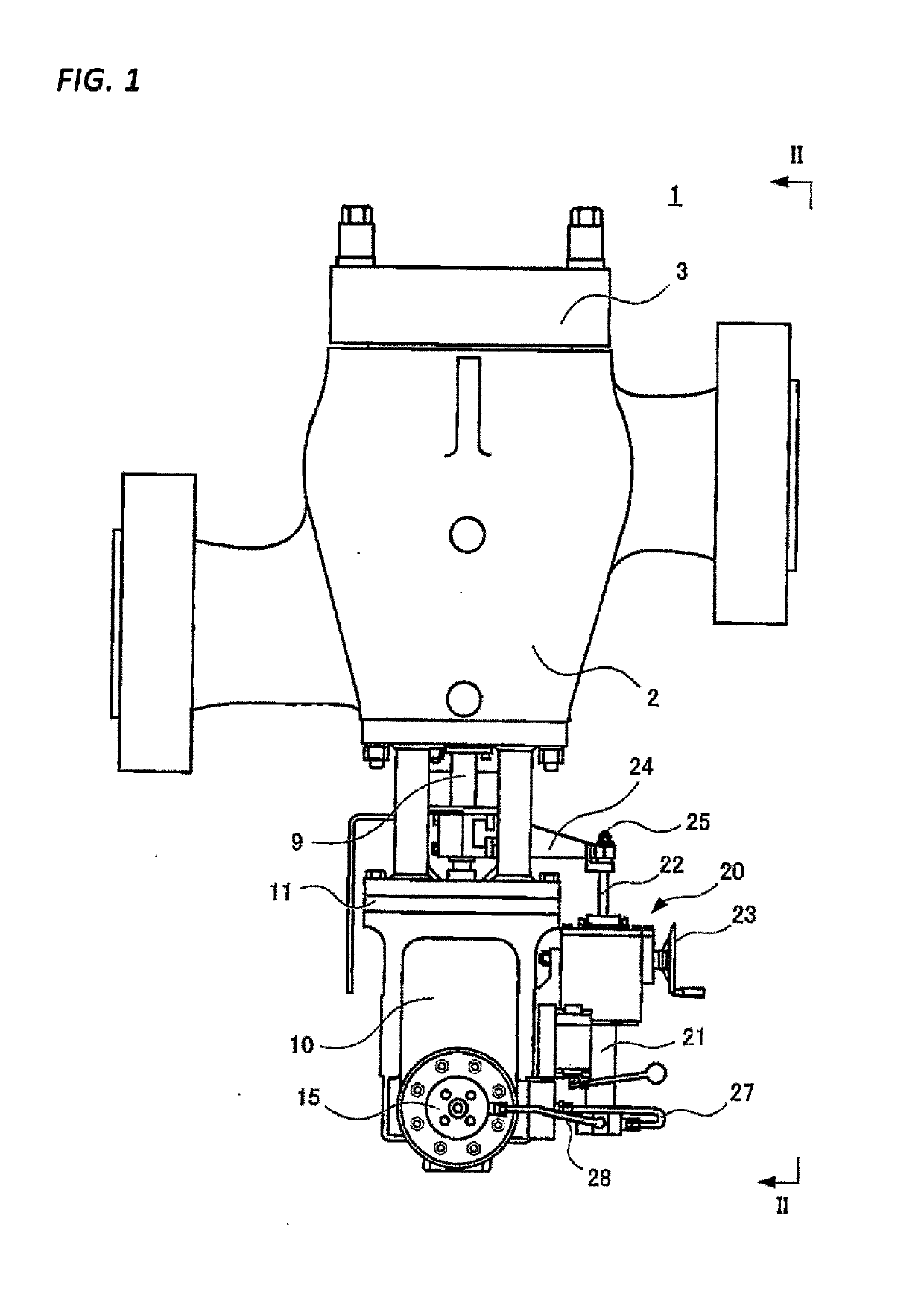
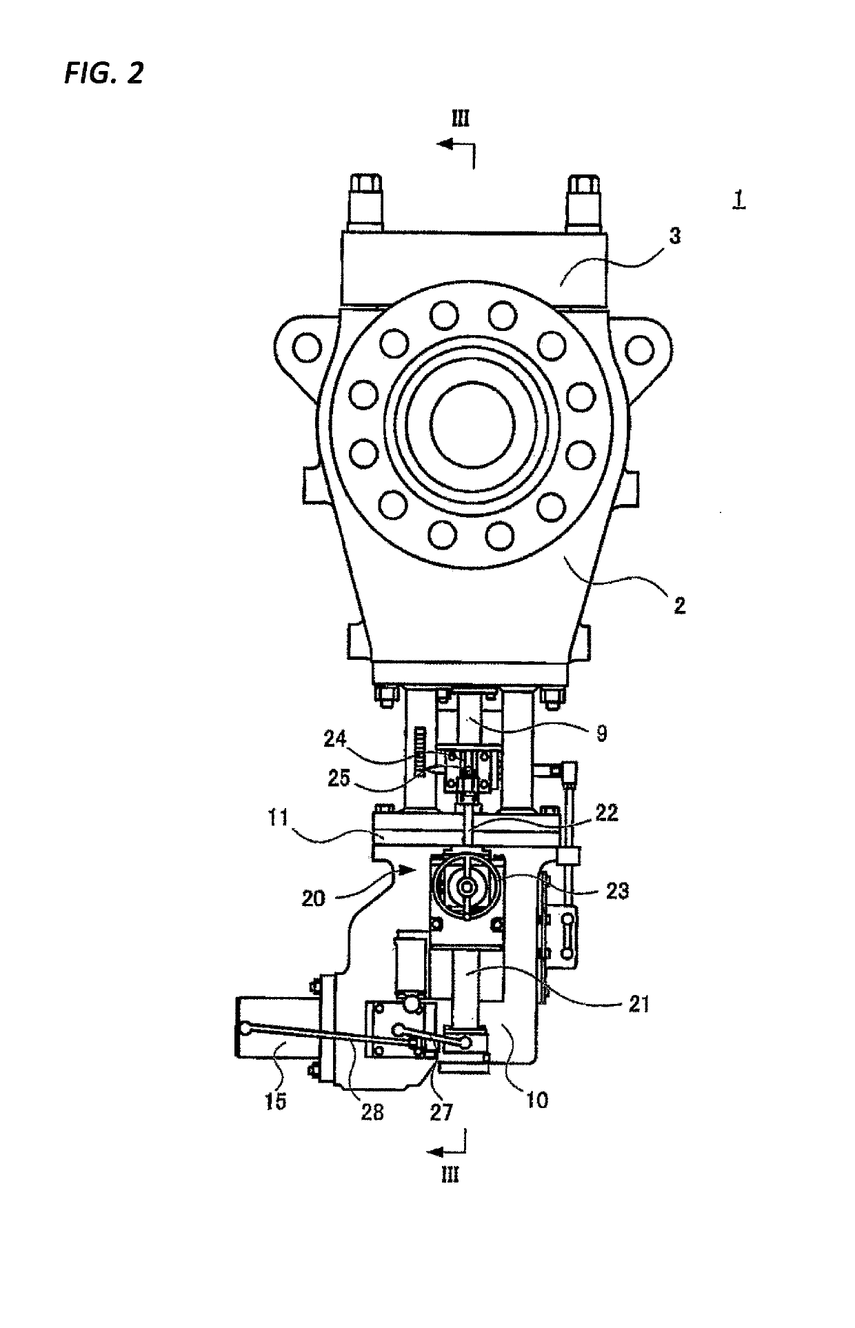
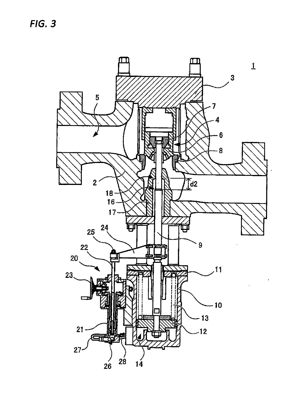
[0025]First, with reference to FIGS. 1 to 3, the overall configuration of a main stop valve 1 according to an embodiment of the present disclosure will be described. The main stop valve 1 is a hydraulic differential type T&T valve. FIG. 1 is a front view of the main stop valve 1. FIG. 2 is a side view of the main stop valve 1 (a view taken along a line II-II illustrated in FIG. 1). FIG. 3 is a vertical sectional view of the main stop valve 1 (a view taken along a line illustrated in FIG. 2).

[0026]The main stop valve 1 is a T&T valve that closes a steam passage 5 by a valve body 4 installed inside a casing 2 and a casing cover 3. As illustrated in FIG. 3, in the present embodiment, the valve body 4 includes a main valve 6 and a balance valve 7. A valve rod 9 connected to the valve body 4 is lowered, and when the valve body 4 is seated on a valve ...


PUM


Abstract

A main stop valve includes: a hydraulic cylinder; a piston arranged in a hydraulic cylinder; a valve rod connected to the piston; and a valve body connected to the valve rod and configured to block a steam passage. The main stop valve further includes: a pilot cylinder having a communication port in fluid communication with the hydraulic cylinder; a rod connected in parallel with the valve rod and configured to be inserted from one end of the pilot cylinder; a sliding ring provided on the rod; and a pilot sleeve configured to be slidably fitted into an inner surface of the pilot cylinder and slidably fitted into an outer peripheral surface of the sliding ring in a section between the one end of the pilot cylinder and the communication port.

Description

TECHNICAL FIELD[0001]The present disclosure relates to a main stop valve installed at an inlet of a steam turbine or the like.BACKGROUND[0002]A main stop valve installed at an inlet of a steam turbine or the like is capable of being closed quickly to block steam and being opened gradually during startup to adjust the supply amount of steam. A trip and throttle (T&T) valve is generally used as such a main stop valve. For example, in the case of a hydraulic-actuation type T&T valve, hydraulic oil is supplied to a cylinder during operation, and the valve is kept open by applying a hydraulic pressure exceeding the pressing force of a spring to a piston. In an emergency, a path configured to rapidly drain the hydraulic oil from the cylinder is opened, and the piston to which the hydraulic pressure is not applied is pushed down by the pressing force of the spring, thereby closing the valve quickly.[0003]In the meantime, when a hydraulic-actuation type T&T valve is started, the valve is gr...

Claims


Application Information

Patent Timeline
IPC IPC(8): F16K1/30F01D17/10
CPCF16K1/305F01D17/10F01D17/26F01D21/16F16K31/143F01D17/145F01D21/00
Inventor OKAMOTO, SHINJIKAMIJIMA, TERUOSHIBATA, RYOHEIMIURA, WATARU
Owner ELLIOTT EBARA TURBOMACHINERY CORP
Why Eureka
Eureka Blog
Learn More