Differential magnetic load cells for compact low-hysteresis force and torque measurements

Active Publication Date: 2019-05-16
MASSACHUSETTS INST OF TECH
View PDF0 Cites 1 Cited by
  • Summary
  • Abstract
  • Description
  • Claims
  • Application Information

AI Technical Summary

Benefits of technology

The patent describes a device that uses magnetic field sensors to measure the movement of a magnet attached to a frame. The sensors are placed tightly together to create a sharp field boundary between them. When the frame is moved or a force is applied, the sensors detect the change in magnetic field. This change can be measured and processed to determine the force or torque applied. This device can be used to create a precise measurement of movement and force in various applications such as medical devices or sports equipment.

Problems solved by technology

It is a well-known problem that strain gauge bonds can exhibit hysteresis, be temperature dependent, and can, in general, be a point of failure of the device.
Prior art non-contact position measurements have historically not had high enough resolution for load cell applications, but have been used commonly for applications that can tolerate larger displacements.
An important disadvantage to these prior art techniques is that relatively large overlapping areas are required for a low noise measurement.
In many compact load cell applications (particularly for measuring many degrees of freedom), realizing these geometries can be challenging.

Method used


Image

  • Differential magnetic load cells for compact low-hysteresis force and torque measurements
  • Differential magnetic load cells for compact low-hysteresis force and torque measurements
  • Differential magnetic load cells for compact low-hysteresis force and torque measurements

Examples


examples of particular embodiments

Single Axis Device

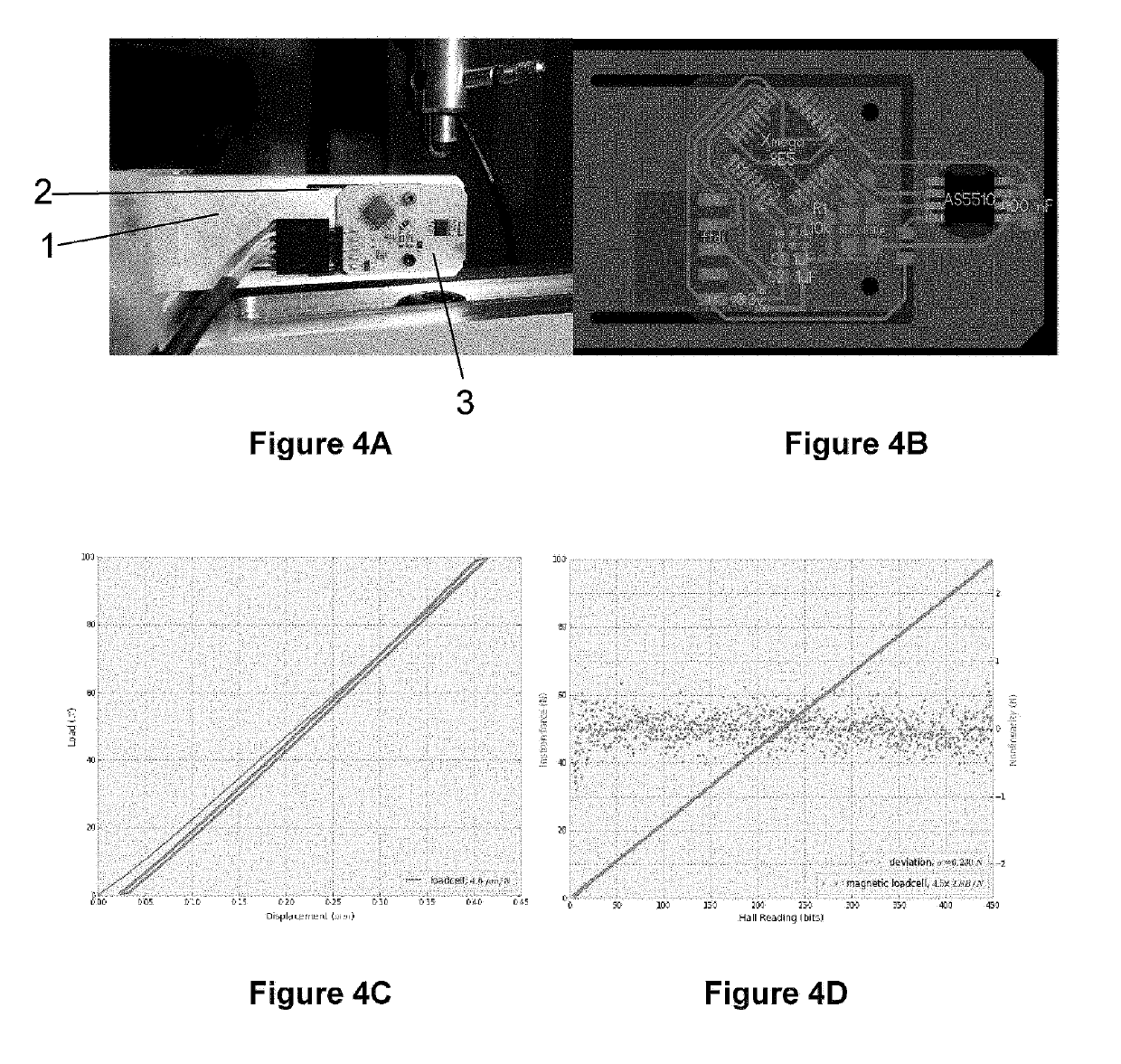
[0040]The first example of a differential magnetic load cell is a single axis measurement device based on the Austrian Microsystems AS5510 10 bit linear encoder IC, which boasts 500 nm resolution. This prototype is shown in FIG. 4A with its circuit board layout shown in FIG. 4B. The circuit board (3) is mounted to a piece of waterjet aluminum (1) with a flexure (2) cut into it. A magnet rests in a hole on the moving part of the flexure. The flexure is designed to have a stiffness of approximately 5 um / Newton. The encoder needs an air gap of less than 1 mm, so the board is milled away inside the SOIC-8 footprint where the AS5510 chip is mounted and the part is flipped over to bring it closer to the magnet underneath. The device uses an 8 mm circular diametrically magnetized magnet. The chip can be operated at its highest sensitivity (+−12.5 mT full scale) and in slow mode (12.5 KHz as opposed to 50 KHz, but with 0.5 mT peak-to-peak noise as opposed to 0.8 mT).

[0041]...


PUM


Abstract

Magnetic load cells that measure force and / or torque are constructed from magnets and one or more arrays of magnetic field sensors. The magnetic field sensors are structured in a tight array where the array is attached to a first portion of a frame. The magnets are operated in pairs polarized in opposition to one-another. In particular, pairs of concentric magnets create sharp field boundaries. The magnets are attached to a second portion of the frame with the magnets separated from the array of field sensors by a small gap. The second portion of the frame is free to displace or rotate in relation to the first portion of the frame when a force or torque is applied to it. The displacement results in a measurable differential change in magnetic field reported by the array that can be sampled and processed to relate to the applied force or torque.

Description

[0001]This application is related to, and claims priority from, U.S. Provisional patent application No. 62 / 584,302 filed Nov. 10, 2017. Application 62 / 584,302 is hereby incorporated by reference in its entirety.BACKGROUNDField of the Invention[0002]The present invention relates generally to the field of force and torque measurement and more particularly to differential magnetic load cells that are compact and have low hysteresis for such measurements.Description of the Problem Solved[0003]Force measurement is an essential technology across a range of disciplines, including robotics, medicine, materials, manufacturing, metrology, and many others. Many applications require a transducer with very high stiffness, so that the displacements induced by the measured forces are very small. These measurements are commonly performed by measuring the strain of a structure. Typically, this is done using a strain gauge which is bonded to a surface of a structural member. When the structure experi...

Claims


Application Information

Patent Timeline
IPC IPC(8): G01R33/038G01R33/00G05G9/047
CPCG01R33/0385G01R33/0094G05G9/047G05G2009/04755
Inventor CALISCH, SAMUEL E.GERSHENFELD, NEIL A.
Owner MASSACHUSETTS INST OF TECH
Why Eureka
Try Eureka