Method for setting up a molding system

a molding system and molding technology, applied in the direction of process and machine control, program control, instruments, etc., can solve the problems of large number of trial molding operations, long set-up period, and difficulty in forming products of consistent quality, so as to reduce the volumetric difference

Active Publication Date: 2019-05-23
CORETECH SYST CO LTD
View PDF3 Cites 4 Cited by
  • Summary
  • Abstract
  • Description
  • Claims
  • Application Information

AI Technical Summary

Benefits of technology

[0012]In some embodiments, the method further comprises increasing a packing pressure of the molding machine if the detected volumetric property is greater than the predetermined volumetric property.
[0013]In some embodiments, the method further comprises decreasing a packing pressure of the molding machine if the detected volumetric property is less than the predetermined volumetric property.
[0016]In some embodiments, the method further comprises adjusting a packing pressure profile of the molding machine to reduce a volumetric difference between the detected state waveform and the predetermined state waveform.
[0020]In some embodiments, the method further comprises adjusting a packing pressure profile of the molding machine to reduce a volumetric difference between the first detected state waveform and the second detected state waveform.
[0023]In some embodiments, the method further comprises adjusting a packing pressure profile of the second molding machine to reduce a volumetric difference between the detected state waveform and the predetermined state waveform.

Problems solved by technology

Therefore, it is difficult to form products of a consistent quality.
In general, the setting of molding parameters of the injection molding machine requires a large number of trial molding operations and a lengthy set-up period because the set-up work greatly depends on the knowledge and experience of an operator of the injection molding machine, and because various parameters affect one another.

Method used


Image

  • Method for setting up a molding system
  • Method for setting up a molding system
  • Method for setting up a molding system

Examples


Embodiment Construction

[0068]The following description of the disclosure accompanies drawings, which are incorporated in and constitute a part of this specification, and illustrate embodiments of the disclosure, but the disclosure is not limited to the embodiments. In addition, the following embodiments can be properly integrated to complete another embodiment.

[0069]References to “some embodiments of the present disclosure,”“an embodiment,”“exemplary embodiment,”“other embodiments of the present disclosure,”“another embodiment,” etc. indicate that the embodiment(s) of the disclosure so described may include a particular feature, structure, or characteristic, but not every embodiment necessarily includes the particular feature, structure, or characteristic. Further, repeated use of the phrase “in the embodiment” does not necessarily refer to the same embodiment, although it may.

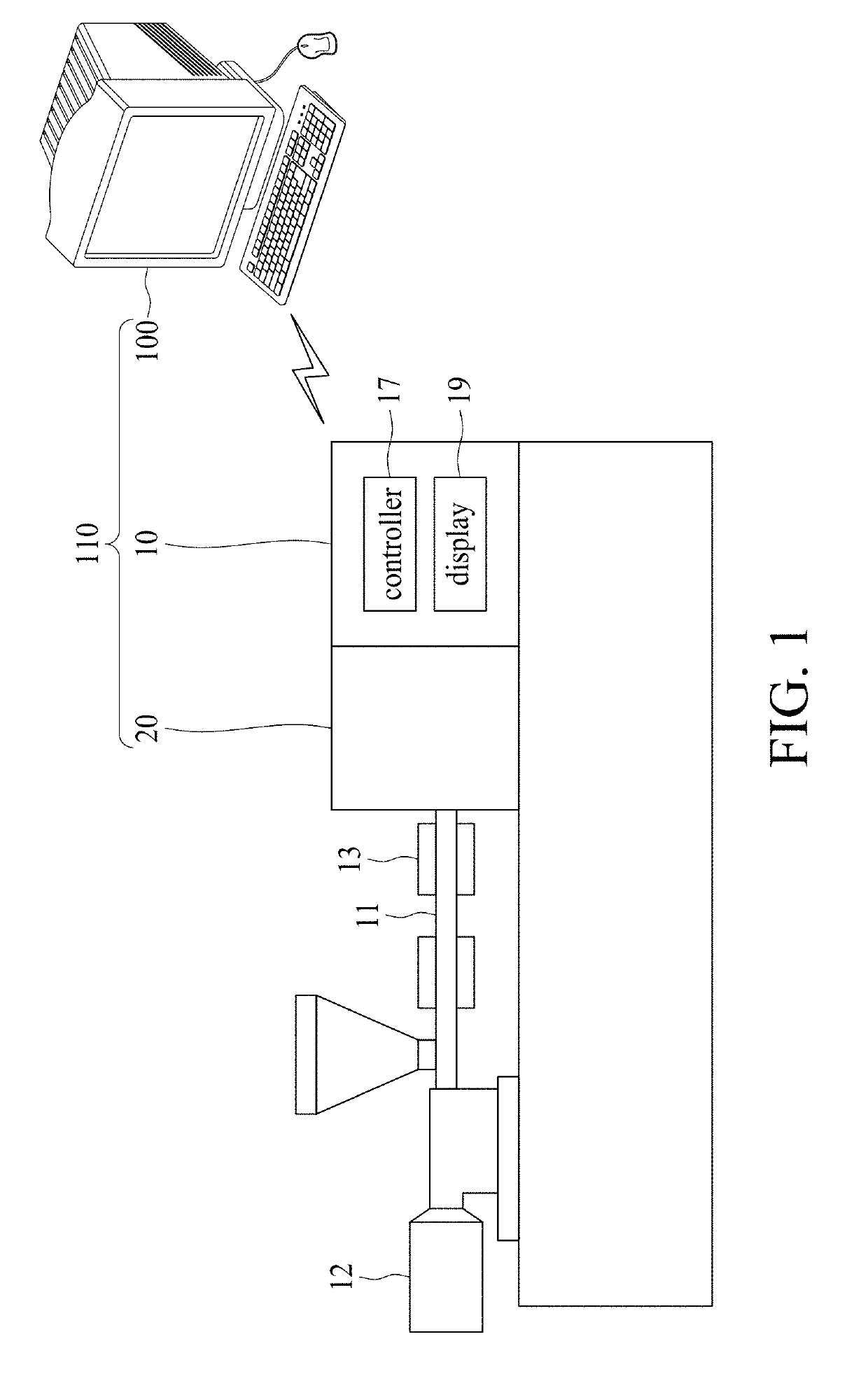
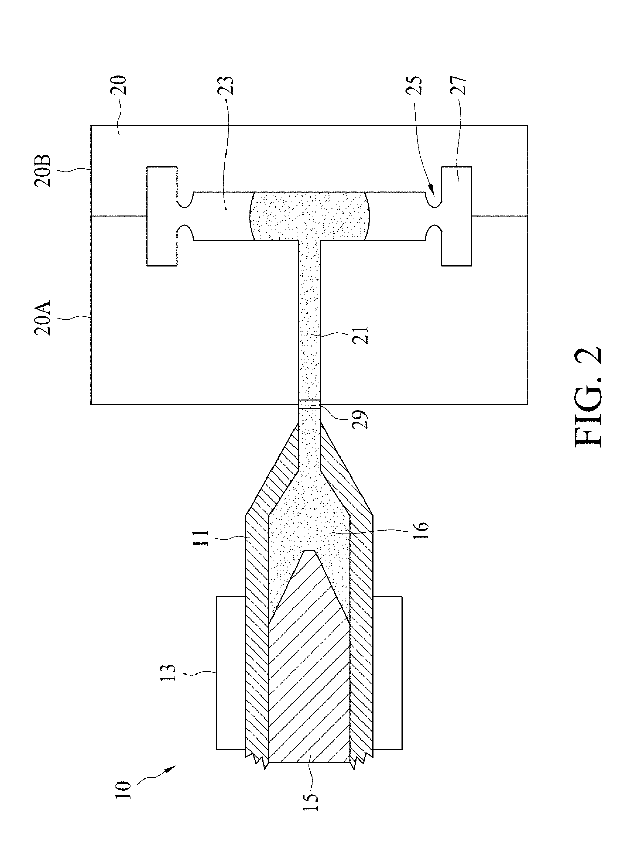
[0070]The present disclosure is directed to a molding system capable of setting molding parameters using multiple in-mold PVT (Pre...


PUM

PropertyMeasurementUnit
melting temperatureaaaaaaaaaa
pressureaaaaaaaaaa

Abstract

The present disclosure provides a method for operating a molding system. The molding system includes a molding machine and a mold disposed on the molding machine, wherein the mold has a mold cavity for being filled with a molding material from the molding machine. The method comprises a step of obtaining a predetermined state waveform expressing a predetermined volumetric variation of the molding material. Next, the method further comprises obtaining a measured pressure and a measured temperature of the molding material in the mold cavity while performing a molding process for filling the molding material into the mold cavity. Next, the method includes obtaining a detected volumetric property of the molding material corresponding to the measured pressure and the measured temperature. Subsequently, the method comprises displaying the detected volumetric property of the molding material with the predetermined state waveform.

Description

CROSS-REFERENCE TO RELATED APPLICATION[0001]This application is a continuous-in-part application of U.S. application Ser. No. 15 / 821,834, filed on Nov. 23, 2017, which is incorporated herein by reference in its entirety.TECHNICAL FIELD[0002]The present disclosure relates to a method for setting up a molding system, and more particularly, to a method for fine-tuning a molding system using multiple in-mold PVT (Pressure-Specific Volume-Temperature) waveforms of the molding material.DISCUSSION OF THE BACKGROUND[0003]Injection molding is a technology commonly used for high-volume manufacturing of parts made of synthetic resin, most commonly thermoplastic polymers. During a repetitive injection molding process, a plastic resin, most often in the form of small beads or pellets, is introduced to an injection molding machine that melts the resin beads under heat, pressure, and shear. The resulting molten resin is forcefully injected into a mold cavity having a particular cavity shape. The i...

Claims


Application Information

Patent Timeline
Patent Type & Authority Applications(United States)
IPC IPC(8): B29C45/77B29C45/76B29C45/78
CPCB29C45/77B29C45/7693B29C45/78B29C2045/7606B29C2945/76006B29C2945/7604B29C2945/76257B29C2945/76381G05B2219/37399G05B2219/37431G05B2219/45244G06F2217/16G06F2217/41G06F2113/22G06F30/23G06F2111/10
Inventor CHANG, YUINGCHANG, RONG-YEUHSU, CHIA-HSIANGCHANG, CHUAN-WEICHIEN, CHING-CHANG
Owner CORETECH SYST CO LTD
Why Eureka
Try Eureka