Vehicle front section structure and vehicle front section coupling method

a technology for front sections and coupling methods, which is applied in the directions of propulsion parts, electric propulsion mounting, transportation and packaging, etc., to achieve the effect of simple operation

Inactive Publication Date: 2019-05-23
TOYOTA JIDOSHA KK
View PDF20 Cites 7 Cited by
  • Summary
  • Abstract
  • Description
  • Claims
  • Application Information

AI Technical Summary

Benefits of technology

[0004]In consideration of the above circumstances, an object of the present disclosure is to obtain a vehicle front section structure and a vehicle front section coupling method enabling a suspension and a vehicle body-side member to be assembled by a simple operation.
[0007]Moreover, the chassis module and the vehicle body-side member can be assembled by a simple operation by overlapping the chassis module and the rear coupling member that is disposed at the vehicle front side of the vehicle body-side member along the vehicle front-rear direction, and by fastening the chassis module and the rear-side coupling member together with the fastener from the vehicle width direction outer side.
[0011]In the vehicle front section structure of the third aspect, each of the two suspension towers is fastened to each of the two extending front side members at a position that does not overlap with each of the two suspensions. This thereby enables a simple fastening operation, in which the suspensions do not cause an obstruction.
[0015]In the vehicle front section structure of the fifth aspect, each of the two built-in front side members and each of the two projecting side members can be fastened together at a position that does not overlap with the suspension, thereby enabling a simple fastening operation, in which the suspension does not cause an obstruction.
[0018]According to the vehicle front section coupling method of the sixth aspect, the chassis module and the rear coupling member are moved relative to each other in the vehicle front-rear direction such that their respective fastening portions overlap as seen from a vehicle side. Manufacturing equipment to move the vehicle body in a vehicle vertical direction is thus not needed. Moreover, since the chassis module and the rear coupling member are fastened from the vehicle width direction outer side at the fastening portions, assembly can be performed by a simple operation.
[0019]The vehicle front section structure and vehicle front section coupling method according to the present disclosure enable a suspension and a vehicle body-side member to be assembled by a simple operation.

Problems solved by technology

Manufacturing equipment to move the vehicle body in a vertical direction is thus necessary in a cumbersome assembly operation.

Method used


Image

  • Vehicle front section structure and vehicle front section coupling method
  • Vehicle front section structure and vehicle front section coupling method
  • Vehicle front section structure and vehicle front section coupling method

Examples


first exemplary embodiment

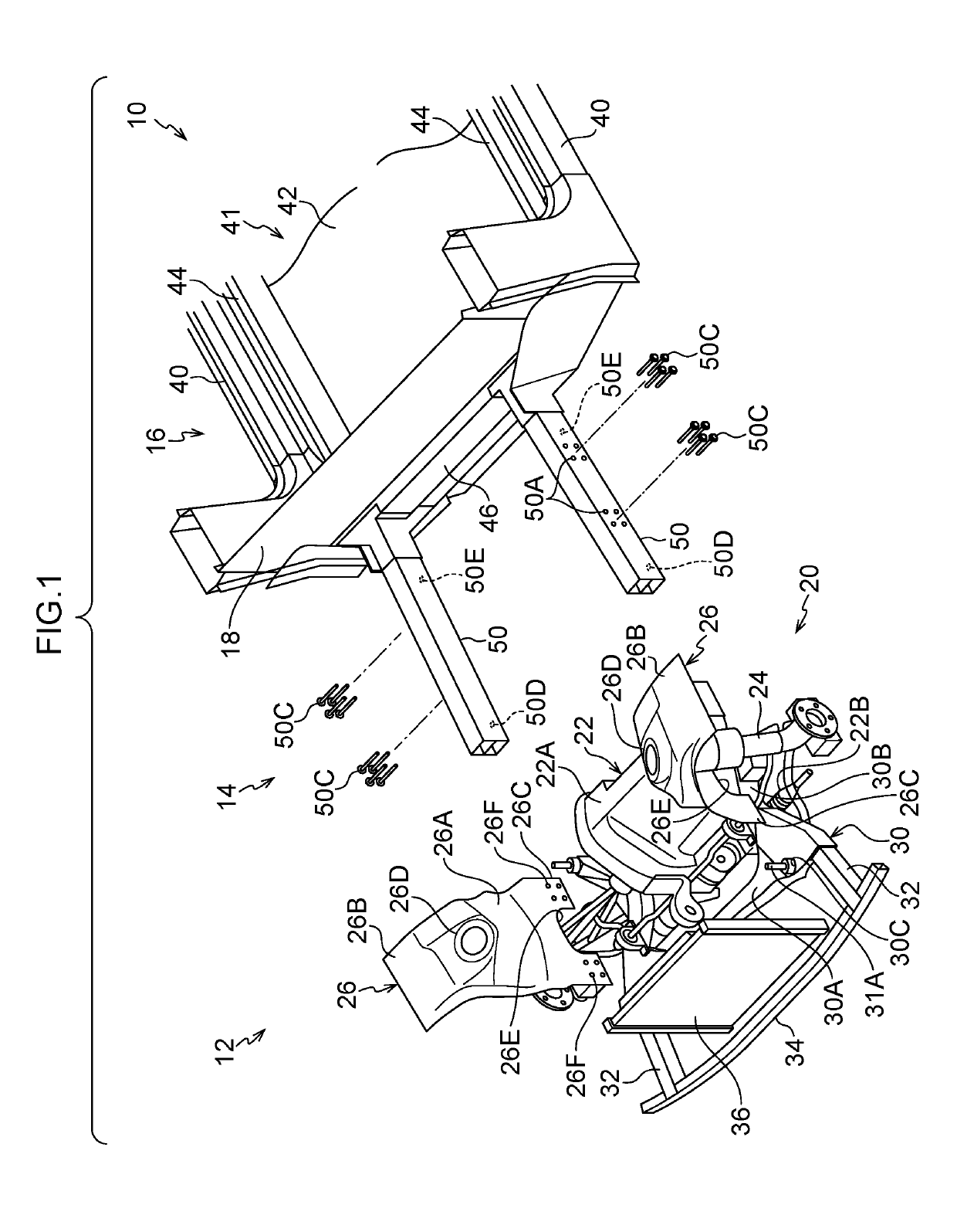
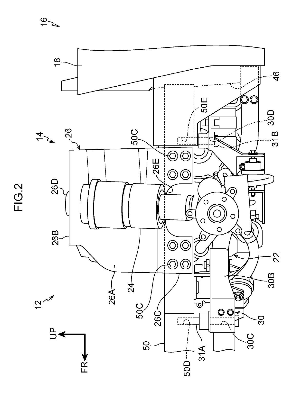
[0025]Explanation follows regarding a vehicle front section structure 12 according to a first exemplary embodiment of the present disclosure, with reference to FIG. 1 and FIG. 2. Note that in the drawings, arrow FR, arrow UP, and arrow W respectively indicate a front direction (direction of travel), an upper direction, and a width direction of the vehicle, as appropriate. In the following explanation, unless specifically indicated otherwise, reference simply to the front and rear, width, and upward and downward directions refers to the front and rear in a vehicle front-rear direction, the vehicle width direction, and upward and downward in a vehicle vertical direction.

[0026]As illustrated in FIG. 1, the vehicle front section structure 12 according to the present exemplary embodiment is applied to a front section of a vehicle 10, such as an electric vehicle, and includes a power unit chamber 14 and a vehicle cabin 16. The power unit chamber 14 and the vehicle cabin 16 are partitioned...

second exemplary embodiment

[0043]Next, explanation follows regarding a second exemplary embodiment of the present disclosure. In the present exemplary embodiment, portions similar to those of the first exemplary embodiment are allocated the same reference numerals, and detailed explanation thereof is omitted.

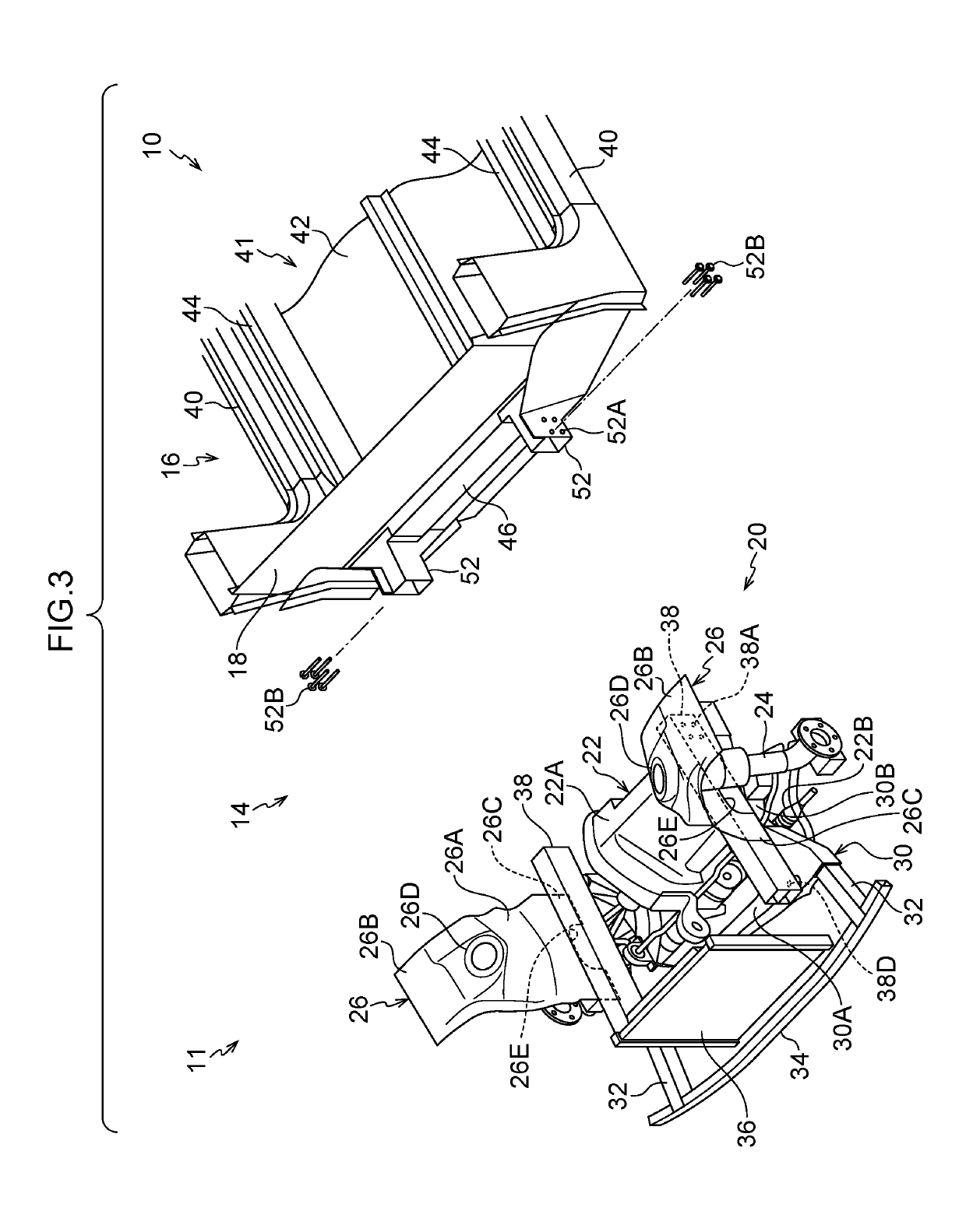
[0044]As illustrated in FIG. 3 and FIG. 4, a vehicle front section structure 11 of the present exemplary embodiment includes projecting side members 52 instead of the extending front side members 50 of the first exemplary embodiment. The chassis module 20 is provided with built-in front side members 38 in addition to the configuration of the chassis module 20 of the first exemplary embodiment.

[0045]The built-in front side members 38 are configured by members similar to the extending front side members 50, and configure vehicle framework members configured with a square tube shaped closed cross-section structure formed with a cross-section resembling two rectangular shapes disposed one above the other. The...


PUM


Abstract

A vehicle front section structure includes: a chassis module configured to be disposed at a vehicle front section, and including a drive unit, a suspension, and a suspension tower disposed upright at a vehicle width direction inner side of the suspension with the suspension being attached to the suspension tower; a rear-side coupling member configured to be disposed at a vehicle front side of a vehicle body-side member that is disposed further toward a vehicle rear than the chassis module, overlapping with the chassis module along a vehicle front-rear direction, and being coupled to the chassis module; and a fastener that fastens the chassis module and the rear-side coupling member together from a vehicle width direction outer side.

Description

CROSS-REFERENCE TO RELATED APPLICATION[0001]This application claims priority under 35 USC 119 from Japanese Patent Application No. 2017-223394 filed Nov. 21, 2017, the disclosure of which is incorporated by reference herein in its entirety.BACKGROUNDTechnical Field[0002]The present disclosure relates to a vehicle front section structure and a vehicle front section coupling method.Related Art[0003]Japanese Patent Application Laid-Open (JP-A) No. 2012-144142 discloses an electric vehicle in which a drive unit is coupled to a front side frame by a mounting device, and including a suspension tower and a suspension cross member that supports a suspension. In an electric vehicle configured as in JP-A No. 2012-144142, when attaching the suspension to the suspension tower, this being a vehicle body-side member, the suspension tower needs to be disposed above the suspension to perform assembly. Manufacturing equipment to move the vehicle body in a vertical direction is thus necessary in a cu...

Claims


Application Information

Patent Timeline
Patent Type & Authority Applications(United States)
IPC IPC(8): B62D65/12B62D21/11B62D21/02B62D25/08B62D27/06B62D21/15
CPCB62D65/12B62D21/11B62D21/02B62D25/085B62D27/065B62D21/152B60K1/00B62D25/088B62D65/04B60K2001/001
Inventor SHIMIZU, KAZUKI
Owner TOYOTA JIDOSHA KK
Why Eureka
Try Eureka