

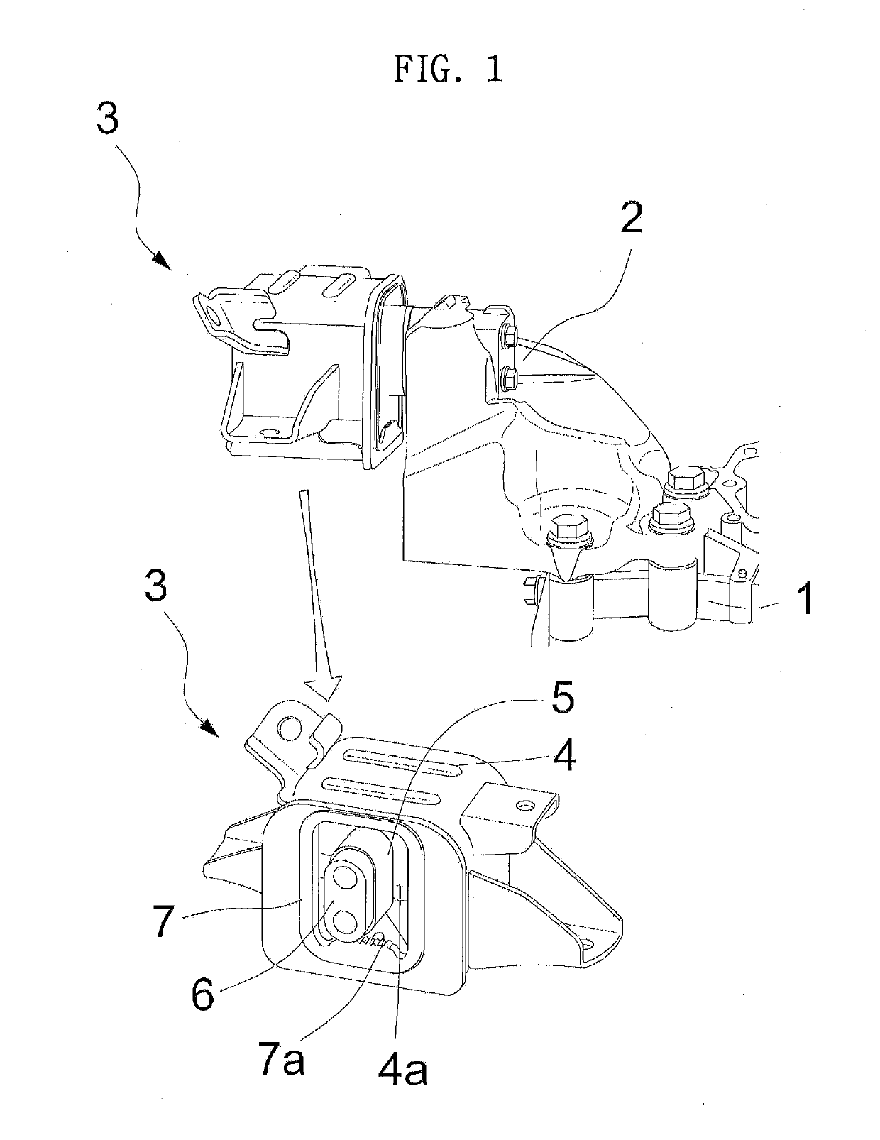
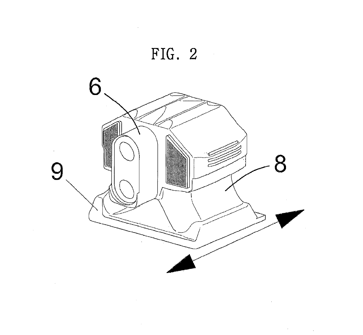
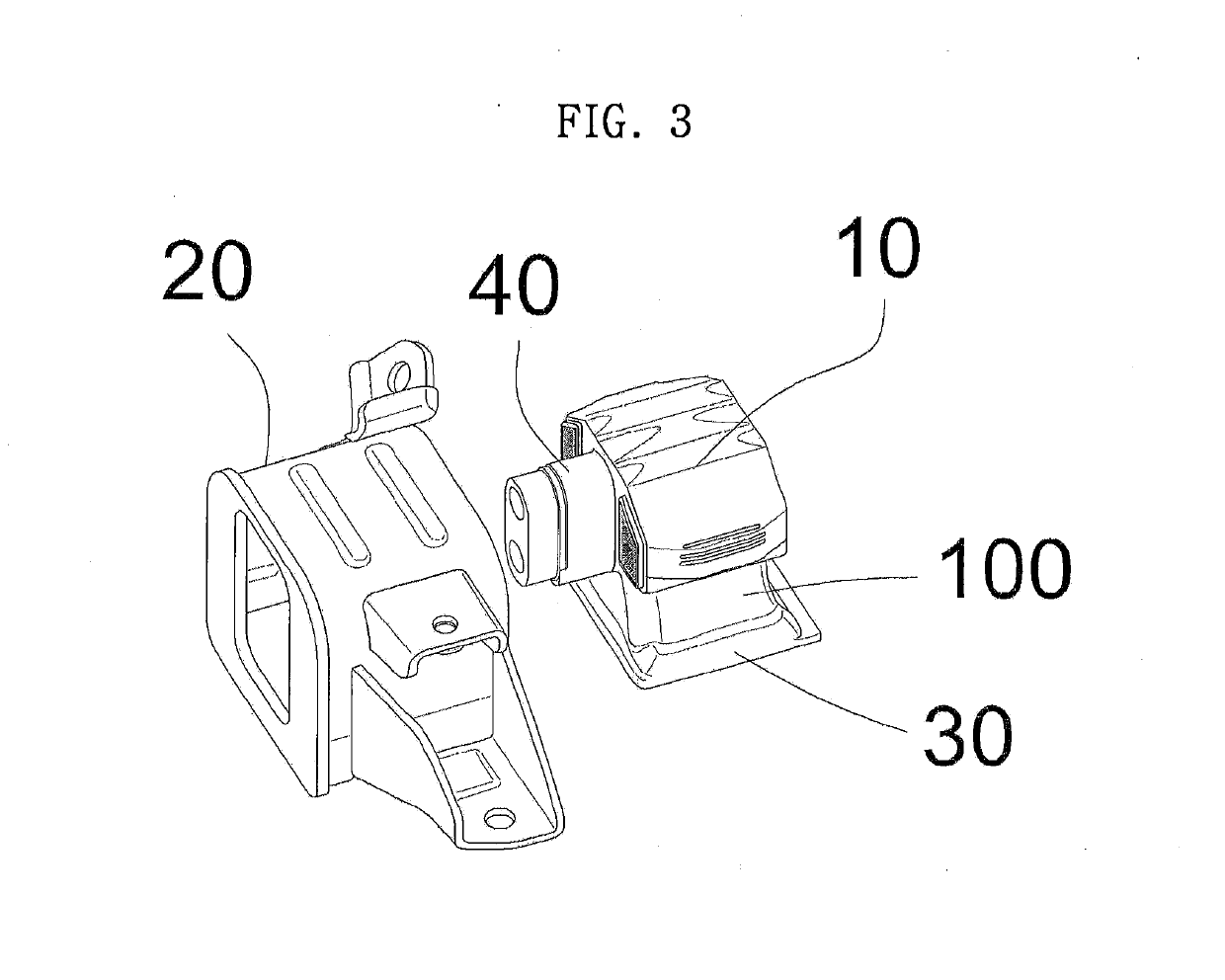
Stopper for transmission mount
a technology for stopping parts and mounts, which is applied in the direction of vehicle sub-unit features, jet propulsion mountings, shock absorption devices, etc., can solve the problems of reducing integrity, affecting the handling performance of vehicles, and affecting the durability of attachments, so as to improve the spring properties of rubber, reduce costs and weight, and improve the effect of additional handling performan
- Summary
- Abstract
- Description
- Claims
- Application Information
AI Technical Summary
Benefits of technology
Problems solved by technology
Method used
Image

Examples
Embodiment Construction
[0035]Hereinafter, embodiments of the present invention will be described in detail with reference to the accompanying drawings so that those skilled in the art to which the present invention pertains may easily carry out the present invention. However, embodiments of the present invention may be implemented in various different ways, and is not limited to embodiments described herein.
[0036]A part irrelevant to the description will be omitted to clearly describe embodiments of the present invention, and the same or similar constituent elements will be designated by the same reference numerals throughout the specification.
[0037]Terms or words used in the specification and the claims should not be interpreted as being limited to a general or dictionary meaning and should be interpreted as a meaning and a concept which conform to the technical spirit of the present invention based on a principle that an inventor can appropriately define a concept of a term in order to describe his / her ...
PUM
| Property | Measurement | Unit |
|---|---|---|
| transmission | aaaaa | aaaaa |
| durability | aaaaa | aaaaa |
| weight | aaaaa | aaaaa |
Abstract
Description
Claims
Application Information