Computed tomography (CT) security inspection system with enhanced x-ray shielding

a computed tomography and security inspection technology, applied in the field of xray security inspection systems, can solve the problems of not being able to provide at least six curtains, the effectiveness of these older x-ray security inspection systems is grossly inadequate, and it takes more than six installed curtains to provide them. achieve the effect of speeding up the conveyor belt speed through the system, reducing the cost of installation, and improving the quality of imag

Active Publication Date: 2019-05-23
PHOTO DIAGNOSTIC SYST INC
View PDF4 Cites 4 Cited by
  • Summary
  • Abstract
  • Description
  • Claims
  • Application Information

AI Technical Summary

Benefits of technology

[0016]Yet another approach might be, for a given desired throughput rate, to significantly speed up the conveyor belt speed through the system. This approach would allow the trays to go through the system faster, with more space between the successive trays, so that the lead-containing curtains in the ingoing and outgoing tunnels will have time to come down between successive trays. However, to obtain the same image quality at this higher throughput speed requires a proportionately higher power X-ray source or, alternatively, a significantly larger number of detector rows, or both, and it requires speeding up the rate of rotation of the gantry carrying the X-ray source of the CT scanner. Thus, this approach adds significantly to cost, and increases the power requirements for the system (which is generally not available at the airports and other security-sensitive locations in which the CT security inspection systems must be installed).

Problems solved by technology

However, over the past few years, it has become evident to those responsible for airport security that the effectiveness of these older X-ray security inspection systems is grossly inadequate.
However, this is not the case.
Furthermore, at the high throughput speeds of the CT security inspection systems, where a tray is almost always disposed under (and displacing) some of the curtains, it takes more than six installed curtains to provide the at least six “fully down” curtains at any given time.
However, if this larger number of lead-containing curtains is installed at the ingoing and outgoing tunnels of the CT security inspection system, the lead-containing curtains must be closer to each other (since the length of the ingoing and outgoing tunnels is generally heavily constrained by the space available for the CT security inspection system), and this causes the double problem of (i) the tray must be pushed harder to lift more curtains, and (ii) the curtains do not come “fully down” until after the entire tray has passed by the curtain by a distance which is somewhat greater than at least an additional 30 cm or so (this distance is a function of the height of the trays and the bags or containers loaded in the trays, etc.).
So, simply adding more curtains does not work at all for the higher throughput rate of the CT security inspection systems.
However, with only 30 cm spacing between trays running on a belt moving at 15 cm per second, there is insufficient time for a displaced lead-containing curtain to come back down to its “fully down” position between trays.
Thus, with a throughput rate of 600 trays per hour, and with a conveyor belt speed of 15 cm per second, the lead-containing curtains of the CT security inspection system cannot adequately shield scattered X-rays passing through the ingoing and outgoing tunnels of the CT security inspection system.
In theory, this approach might give the curtains time to come “fully down” between successive trays, but in practice it requires the ingoing and outgoing tunnels to be excessively longer than is generally allowed by the space constraints present at airports and other security-sensitive locations.
However, in practice, this approach does not work because the rotating curtains need to be precisely synchronized with tray movement in order to quickly come down between incoming trays.
Furthermore, this approach does not work at the higher, desired throughput rate of the newer CT security inspection systems, since it is difficult to get enough curtains fully down between the trays to provide the required level of X-ray attenuation.
Aside from the engineering complexity and power requirements needed to make the curtains go up and down fast enough, such an approach is excessively costly, adding significant expense in each ingoing and outgoing tunnel.
While theoretically possible, the difficulty, reliability and power required by such a complicated system has been found to be impractical.
However, to obtain the same image quality at this higher throughput speed requires a proportionately higher power X-ray source or, alternatively, a significantly larger number of detector rows, or both, and it requires speeding up the rate of rotation of the gantry carrying the X-ray source of the CT scanner.
Thus, this approach adds significantly to cost, and increases the power requirements for the system (which is generally not available at the airports and other security-sensitive locations in which the CT security inspection systems must be installed).

Method used


Image

  • Computed tomography (CT) security inspection system with enhanced x-ray shielding
  • Computed tomography (CT) security inspection system with enhanced x-ray shielding
  • Computed tomography (CT) security inspection system with enhanced x-ray shielding

Examples


Embodiment Construction

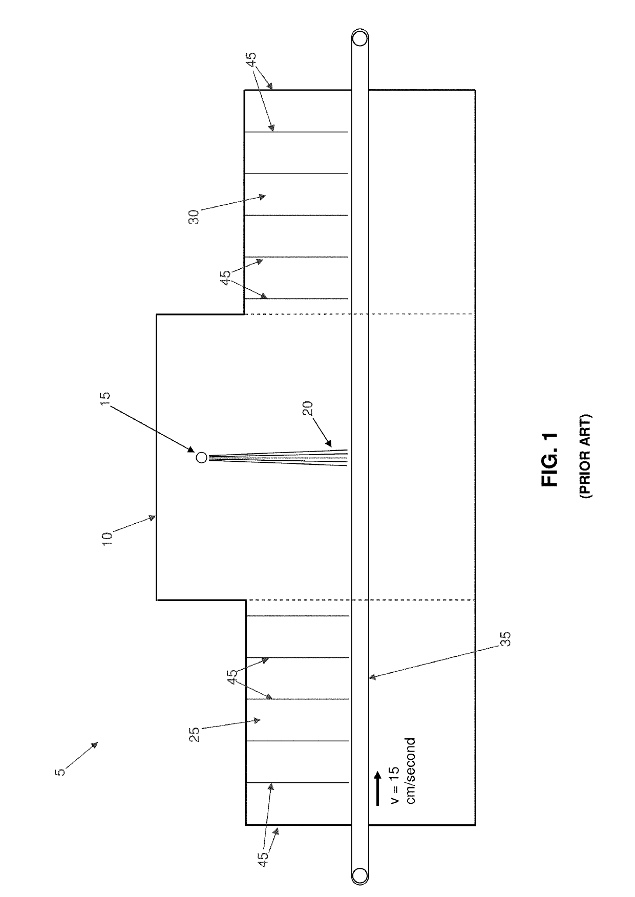
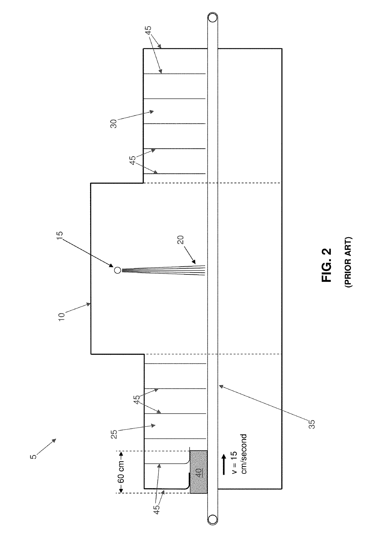
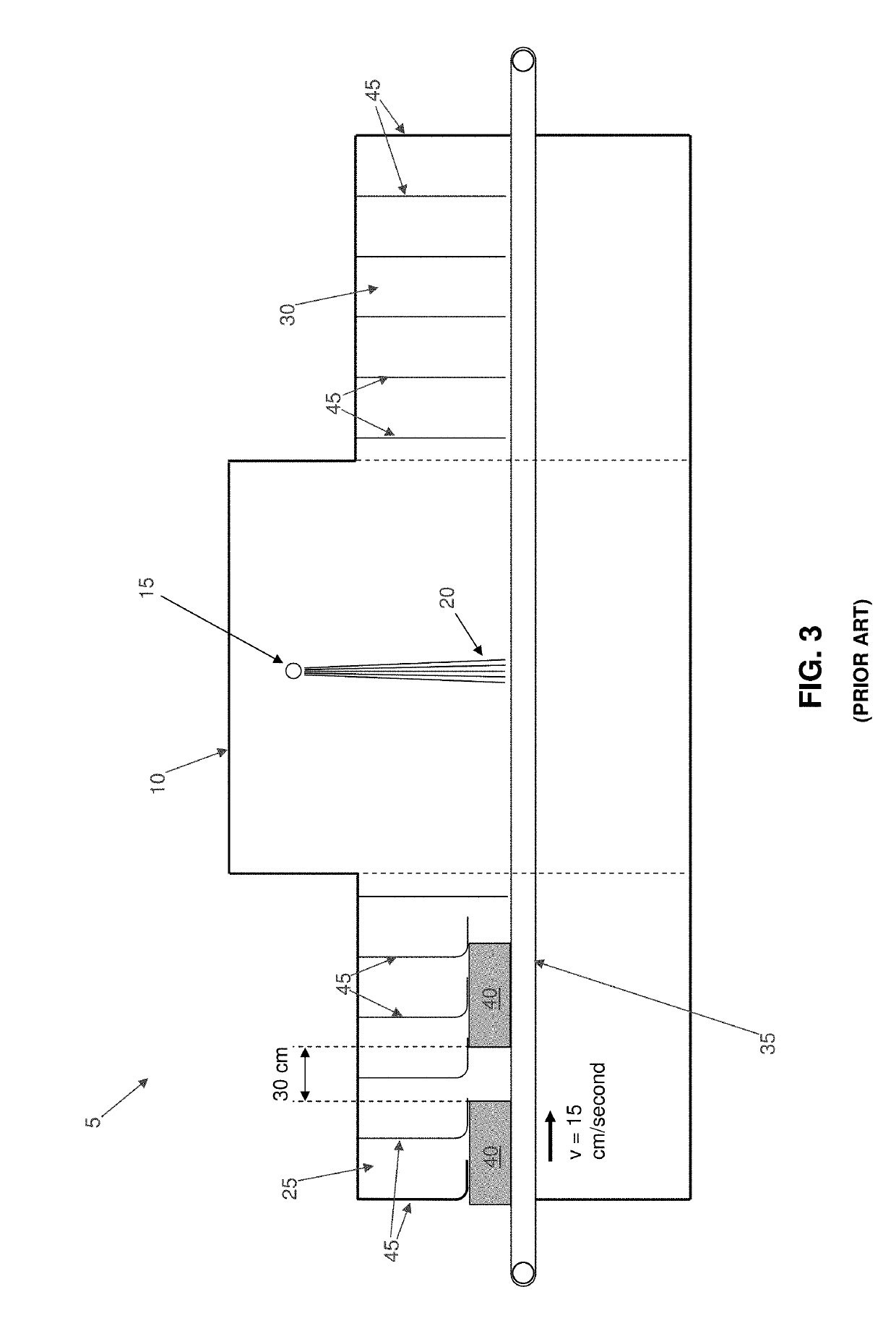
[0033]The present invention comprises the provision and use of a new and improved computed tomography (CT) security inspection system with enhanced X-ray shielding.

[0034]More particularly, to further understand the X-ray shielding problem associated with prior art computed tomography (CT) security inspection systems and to fully appreciate the novel solution to this problem which is provided by the present invention, it should first be recognized that a standard tray length in the U.S. is approximately 60 cm (approximately two feet), and in Europe the standard tray length is approximately 70 cm. As an actual example, it is generally desired to have a CT security inspection system operate at 600 trays per hour. This is one tray every six seconds. Then, at 600 trays per hour, the distance between successive trays would be as follows for various conveyor speeds.

Tray SpacingAverage SpaceAverage Space(at 6 secondsBetween Trays InBetween TraysConveyor Speedper tray)U.S.In EuropeAt 15 cm p...


PUM

PropertyMeasurementUnit
speedaaaaaaaaaa
speedaaaaaaaaaa
thicknessaaaaaaaaaa

Abstract

A method for scanning an object in an X-ray security inspection system, wherein the X-ray security inspection system comprises an ingoing tunnel equipped with radiation-shielding curtains, an X-ray section and an outgoing tunnel equipped with radiation-shielding curtains, the method comprising: passing the object through the ingoing tunnel at a first rate of speed and with a first extent of separation between successive objects; passing the object through the X-ray section at a second rate of speed and with a second extent of separation between successive objects; and passing the object through the outgoing tunnel at a third rate of speed and with a third extent of separation between successive objects; wherein the second rate of speed is less than the first rate of speed and the third rate of speed, and wherein the second extent of separation between successive objects is less than the first extent of separation between successive objects and the third extent of separation between successive objects.

Description

REFERENCE TO PENDING PRIOR PATENT APPLICATION[0001]This patent application claims benefit of pending prior U.S. Provisional Patent Application Ser. No. 62 / 587,798, filed Nov. 17, 2017 by Photo Diagnostic Systems, Inc. and Bernard M. Gordon et al. for COMPUTED TOMOGRAPHY (CT) SECURITY INSPECTION SYSTEM WITH ENHANCED X-RAY SHIELDING (Attorney's Docket No. PDSI-5 PROV), which patent application is hereby incorporated herein by reference.FIELD OF THE INVENTION[0002]This invention relates to X-ray security inspection systems in general, and more particularly to computed tomography (CT) security inspection systems with enhanced X-ray shielding.BACKGROUND OF THE INVENTION[0003]X-ray security inspection systems are widely used at airports and other security-sensitive locations to scan baggage and other containers for explosives and other contraband. These X-ray security inspection systems typically have one (or a few) fixed (i.e., stationary) X-ray sources running at low power (e.g., 2 mA) ...

Claims


Application Information

Patent Timeline
Patent Type & Authority Applications(United States)
IPC IPC(8): G01V5/00G21F3/00G01N23/046G21F1/08
CPCG01V5/005G21F3/00G01N23/046G21F1/085G01N2223/643G01N2223/639G01V5/0016
Inventor GORDON, BERNARD M.JOHNSON, OLOF
Owner PHOTO DIAGNOSTIC SYST INC
Why Eureka
Try Eureka