Photoacoustic probe

a technology of photoacoustic signals and probes, applied in the field of photoacoustic probes, can solve the problems of difficult to transmit data at a predetermined communication rate, inability to store all the measured photoacoustic signals, and inability to obtain data satisfactorily

Inactive Publication Date: 2019-05-30
CANON KK
View PDF0 Cites 0 Cited by
  • Summary
  • Abstract
  • Description
  • Claims
  • Application Information

AI Technical Summary

Benefits of technology

[0011]According to the present invention, it is possible to provide a technique of obtaining data satisfactorily as much using a photoacoustic probe that communicates with a photoacoustic apparatus body.

Problems solved by technology

When a handheld photoacoustic apparatus wirelessly transmits photoacoustic signals based on photoacoustic waves received by a photoacoustic probe to an apparatus body, there is a problem that communication quality may decrease depending on an ambient environment and an apparatus state and it may be difficult to transmit data at a predetermined communication rate.
Moreover, in a case where data is stored in a memory inside a photoacoustic probe, there is a problem that, if there is a small storable data capacity (that is, available capacity), it is not possible to store all the measured photoacoustic signals.

Method used


Image

  • Photoacoustic probe
  • Photoacoustic probe
  • Photoacoustic probe

Examples


first embodiment

Overall Configuration

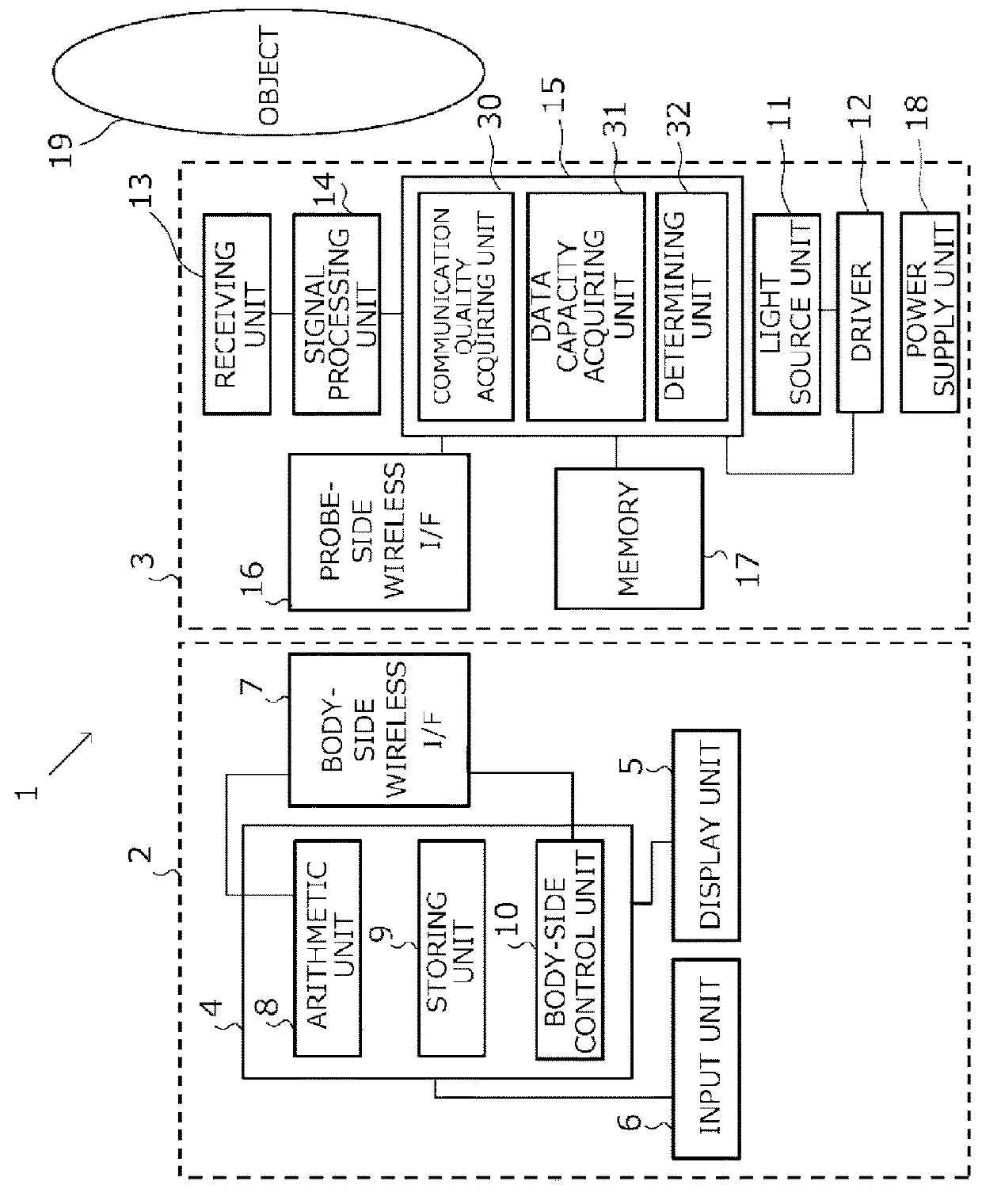
[0026]A configuration of a photoacoustic apparatus 1 according to the present embodiment will be described with reference to a block diagram of FIG. 1. The photoacoustic apparatus 1 includes a photoacoustic apparatus body 2 and a probe 3. The photoacoustic apparatus body 2 includes a computer 4, a display unit 5, an input unit 6, a body-side wireless interface 7 (a body-side wireless I / F). The computer 4 includes an arithmetic unit 8, a storing unit 9, a body-side control unit 10. The probe 3 includes a light source unit 11, a driver 12, a receiving unit 13, a signal processing unit 14, a probe control unit 15, a probe-side wireless interface 16 (a probe-side wireless I / F), a memory 17, a power supply unit 18.

[0027]The driver 12 drives the light source unit 11 in a first cycle (an emission cycle) under the control of the probe control unit 15 and irradiates pulsed light toward an object 19. In this way, photoacoustic waves is generated from the object 19 in the ...

second embodiment

[0108]A specific embodiment of a method for transmitting photoacoustic signals according to a communication quality will be described. FIGS. 6A to 6D are timing charts of operations of a system according to the present embodiment. FIG. 6A corresponds to a case in which the communication environment is “good” and is a timing chart in which light is irradiated at the first cycle (emission cycle) to acquire photoacoustic signals and data is transmitted at the first communication rate. In a case where the communication quality is good, since all photoacoustic signals obtained by one radiation of light can be transmitted until the next radiation of light, photoacoustic images can be displayed with a high image quality and a high frame rate.

[0109]FIG. 6B illustrates a process in a case where the communication environment is “bad” and the available memory capacity is “sufficient”. In this example, similarly to FIG. 6A, radiation of light and acquisition of photoacoustic signals are perform...


PUM

PropertyMeasurementUnit
wavelengthaaaaaaaaaa

Abstract

A photoacoustic probe comprising: a receiving unit configured to receive photoacoustic waves generated from an object irradiated with light; a signal processing unit configured to perform a process for outputting photoacoustic signals originating from the photoacoustic waves; a communication unit configured to perform wireless communication with a photoacoustic apparatus body to transmit the photoacoustic signals; a communication quality acquiring unit configured to acquire a communication quality of wireless communication which the communication unit performs; a memory configured to store the photoacoustic signals; and a determining unit configured to determine, according to the communication quality, a communication rate of the communication unit and whether to store the photoacoustic signals in the memory.

Description

BACKGROUND OF THE INVENTIONField of the Invention[0001]The present invention relates to a photoacoustic probe.Description of the Related Art[0002]A photoacoustic tomography (PAT) is known as one of methods for obtaining optical characteristic values such as an absorption coefficient inside an object. An apparatus which uses PAT (hereinafter referred to as a photoacoustic apparatus) irradiates pulsed light generated from a light source to a living body. The photoacoustic apparatus receives, using a probe, acoustic waves (photoacoustic waves) generated when light having propagated through the object while diffusing into the object is absorbed by a light absorber. By analyzing this reception signals, an initial acoustic pressure distribution resulting from the light absorber inside the object is obtained. Expression (1) below indicates an acoustic pressure of photoacoustic waves obtained from the light absorber.P=Γ·μa·Φ  (1)[0003]Here, P is an initial acoustic pressure. Γ is a Gruneise...

Claims


Application Information

Patent Timeline
Patent Type & Authority Applications(United States)
IPC IPC(8): A61B8/00G01N29/24A61B8/15A61B5/00
CPCA61B8/4483G01N29/2418A61B8/15A61B5/0095A61B5/0013G01N29/0672A61B8/4416A61B8/56
Inventor OHISHI, SHINJI
Owner CANON KK
Why Eureka
Try Eureka