Digital camera

a digital camera and camera body technology, applied in the field of digital cameras, can solve the problems of frame or the like not being checked at the time of photographing, the operation of the camera becomes very complicated, and the quality of an image is consequentially deteriorated, so as to prevent the effect of dew condensation, improve the effect of photographing, and ensure the effect of good quality

Inactive Publication Date: 2011-03-01
INABA MINORU
View PDF9 Cites 3 Cited by
  • Summary
  • Abstract
  • Description
  • Claims
  • Application Information

AI Technical Summary

Benefits of technology

[0031]In the invention from the second aspect, the indicator lines are matched with predetermined positions of the finder image on the electronic display, and the perspective is visually checked and adjusted. For this reason, in addition to the effect of the invention from the first aspect, the perspective of the image can be visually checked and adjusted accurately, easily and quickly.
[0032]In the invention from the third aspect, dust can be prevented from adhering to the surface of the image pickup element in the camera main body. For this reason, in addition to the effect of the invention from the first or second aspect, improper photographing can be prevented due to the adhesion of dust to the surface of the image pickup element, so that a satisfactory picture can be always obtained stably.
[0033]In the invention from the fourth aspect, the pressure difference between the inside and the outside of the camera main body is mitigated by the flexible partitioning member quickly. For this reason, in addition to the effect from the first, second or third aspect, even in the case where the pressure difference between the inside of the camera main body having the sealed structure and atmospheric air is large due to temperature change, altitude change and the other weather conditions, a strong force is not applied to the flexible partitioning member, so that a satisfactory dew condensation preventing effect can be obtained.

Problems solved by technology

That is to say, firstly, an operation of the camera becomes very complicated.
Secondary, when perspective is controlled by a post-process, a pulse rate is partially changed, and thus the quality of an image is consequentially deteriorated.
Thirdly, since an image to be displayed on a monitor at the time of photographing is an uncorrected image, a finally frame or the like cannot be checked at the time of photographing.
Further, a finished state after the post-process cannot be imaged at the time of photographing.
If photographing is failed, a correction cannot be mostly made by the post-process.
In the case of modernized rigid cameras, however, the perspective control becomes gradually difficult and thus is actually omitted.
For example, in range finder type cameras, the perspective control becomes difficult and then disabled.
The perspective control is revived in single lens reflex cameras, but since special lenses should be used, they become very expensive and are not practical (see of Patent Document 1).
The biggest problem of the lens interchangeable (attachment / detachment) type digital cameras is that dust adheres to image pickup elements, but some of such cameras on the market have a constitution such that lowpass filter etc. provided just in front of the image pickup element is ultrasonically vibrated by crystal resonator so that the dust adhering to the filter is shaken off, and the dust is collected using pressure sensitive adhesive so that re-flying of the dust is prevented.
These cameras, however, do not have the complete dust-proof function.
Lenses for the perspective control in single-lens reflex cameras are very expensive, and their position can be adjust positions only to a single direction due to their constitution.
In actual photographing, therefore, it is not easy to determine the final position.
The digital cameras having the perspective control function, however, cause a difficult problem at the stages of design and manufacturing.
This is because, in order to move an image pickup element at a constant posture, a guide way is normally necessary, and in this case, even very small guide ways require expense and man-hour.
In this case, it is necessary to set the image pickup element so as not to improperly move due to external shock or the like at the time of photographing, and thus the constitution becomes complicated.
In a state where a structural outline is determined at the time of photographing, the lattice-shaped lines do not match with the image in a positional relationship, and thus it is difficult to observe the state of the perspective.
Even if the image circle has margin, however, it is very difficult to make the perspective control in the constitution of the conventional single-lens reflex cameras, but single-lens reflex type (lens interchangeable type) digital cameras have another problem.
The problem is that dust enters the cameras at the time of attaching / detaching lenses so as to adhere to the image pickup elements.
Although the structures become complicated and their manufacturing cost is high, the actual dust removing effect is not perfect.

Method used


Image

  • Digital camera
  • Digital camera
  • Digital camera

Examples


Embodiment Construction

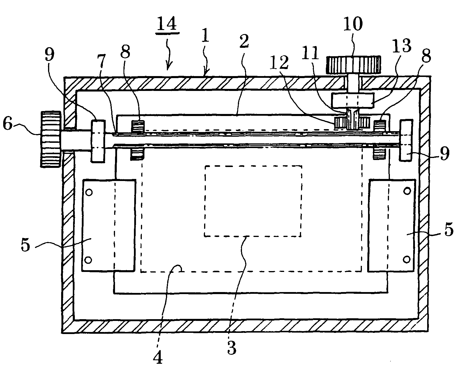
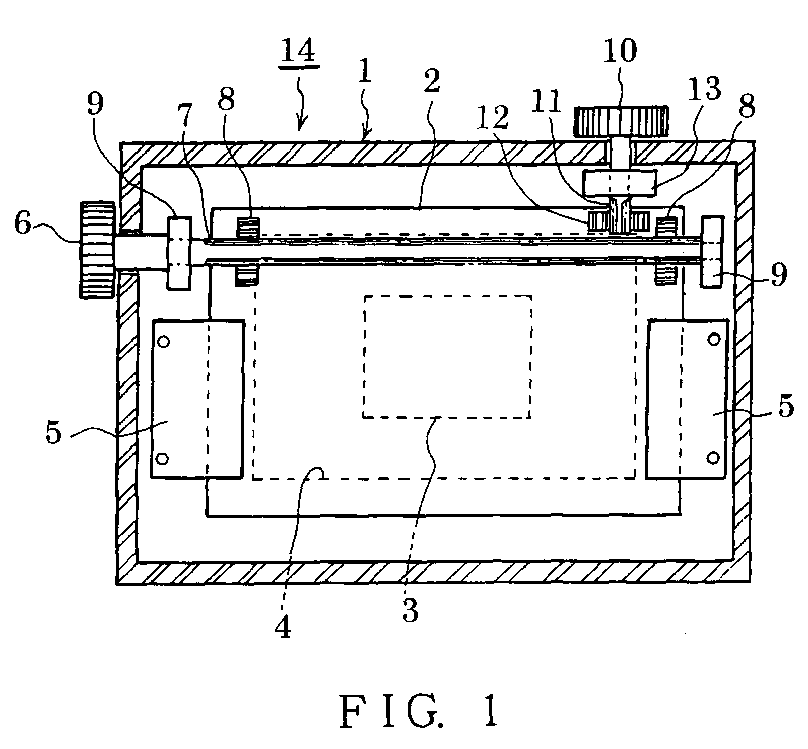
[0044]It is an object to provide an inexpensive digital camera having a simple constitution in which before photographing, perspective is being observed and is simultaneously adjusted suitably, and distortion of an image such as high building is prevented so that a satisfactory picture. This object is realized by providing a perspective control mechanism that moves an image pickup element to a direction vertical to an optical axis of a photographing lens and longitudinal and lateral directions which are perpendicular to each other so as to adjust the image pickup element. In the best embodiment of the present invention, the digital camera includes a longitudinal direction position adjusting mechanism and a lateral direction position adjusting mechanism that press to attach an image pickup substrate mounted with the image pickup element to be attached to a front surface or a rear surface of a frame (body frame) in a camera main body using a plate spring or the like and independently ...


PUM


Abstract

An image pickup substrate mounted with an image pickup element is pressed against the surface of a camera body frame by a plate spring, and exclusive position adjusting mechanisms that independently move the image pickup substrate to a vertical direction and a lateral direction are provided. The image pickup substrate is provided so that its position can be adjusted and a projected image by means of a photographing lens is imaged on the image pickup element. Vertical lines and lateral lines are displayed as software display on an electronic display, and their positions can be independently adjusted to the lateral direction and the vertical direction. A dustproof plate is fixed between an interchangeable lens section and a camera main body, so as to prevent dust from adhering to the surface of the image pickup element.

Description

BACKGROUND OF THE INVENTION[0001]1. Field of the Invention[0002]The present invention relates to a digital camera, and particularly relates to the digital camera having a perspective control function that changes perspective of an image and adjusts visibility on an electronic display so as to photograph the image, and that prevents dust from adhering to an image pickup element.[0003]2. Description of the Related Art[0004]As shown in FIG. 7A, in the case where an entire object 71 such as high building or construction is tried to be photographed by a camera 72, when the camera 72 to be used is normal, an optical axis L of a photographing lens 73 necessarily faces upward. FIG. 7B illustrates the case where relative position relationship between the camera 72 and the object 71 shown in FIG. 7A is constant and the optical axis L of the photographing lens 73 is horizontal. As is clear from FIG. 7B, the image of the object 71 photographed in such a state is seem to tilt backward.[0005]FIG....

Claims


Application Information

Patent Timeline
Patent Type & Authority Patents(United States)
IPC IPC(8): H04N5/225G03B5/08G03B11/04G03B17/02G03B17/14G03B17/18H04N5/232H04N101/00
CPCG02B27/0006G02B27/0068G03B5/06G03B17/14H04N5/217H04N5/2253H04N5/2259H04N23/81H04N23/54H04N23/58
Inventor INABA, MINORU
Owner INABA MINORU
Why Eureka
Try Eureka