
Self-calibrating and autonomous magnetic observatory

a self-calibration and magnetic observatory technology, applied in the field of magnetic observatories, can solve the problems of not providing the vertical of the site, nor the direction of geographic north, and not providing the direction of the geographic north, so as to achieve the effect of improving the quality of the measuremen

Active Publication Date: 2019-05-30
INST ROYAL METEOROLOGIQUE DE BELGIQUE
View PDF0 Cites 3 Cited by
  • Summary
  • Abstract
  • Description
  • Claims
  • Application Information

AI Technical Summary

Benefits of technology

The patent describes an autonomous magnetic observatory that can be installed anywhere and does not require a qualified operator. The measurements are carried out automatically and with higher frequency, resulting in improved precision. The method is cost-effective and self-calibration reduces the drift of the instruments. The combination of automation and self-calibration improves the quality of the measurements and cancels out internal alignment errors. The method is useful for obtaining accurate magnetic field measurements.

Problems solved by technology

Nevertheless, this observatory does not provide an automatic measurement of the direction of the local magnetic field.
It also does not deliver the vertical of the site, nor the direction of geographic north.
Lastly, the method does not allow orthogonality errors that appear over time to be corrected.
Nevertheless, this observatory does not automatically deliver the value of the modulus of the local magnetic field vector, nor the variations in the local magnetic field vector in three directions, nor the direction of geographic north.
No self-calibration method for correcting temperature effects, for measuring the scale factor and for carrying out the orthogonal calibration is proposed.
In conclusion, although these magnetic observatories are often called autonomous observatories, they are in fact only partially autonomous and require an outside intervention to obtain the local magnetic field vector.

Method used


Image

  • Self-calibrating and autonomous magnetic observatory
  • Self-calibrating and autonomous magnetic observatory
  • Self-calibrating and autonomous magnetic observatory

Examples


Embodiment Construction

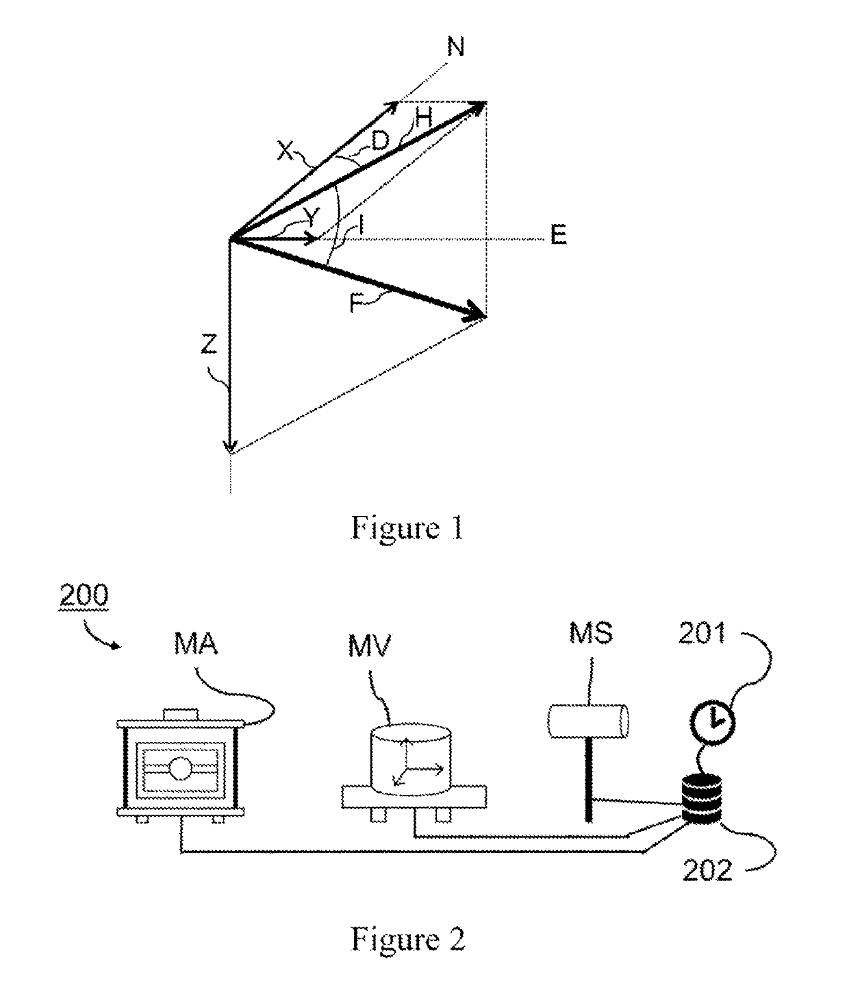
[0051]FIG. 1 shows an example of a local terrestrial magnetic field vector, referred to as the local magnetic field vector {right arrow over (F)} below, and its decomposition into various mathematically independent components. Since the local magnetic field {right arrow over (F)} is a vector field, knowledge of its magnitude is not enough to completely characterize it. Specifically, it is necessary to define its orientation with respect to reference directions. These reference directions are preferably the local vertical (or, equivalently, a horizontal plane) and the direction of geographic north N. The magnetic declination “D” is then defined as being the angle between the geographic north N and the projection of the magnetic vector into a horizontal plane. The magnetic inclination “I” is defined as being the angle between the horizontal plane and the magnetic vector in a vertical plane containing this vector.

[0052]In Cartesian coordinates, XYZ, X points toward geographic north N, ...


PUM


Abstract

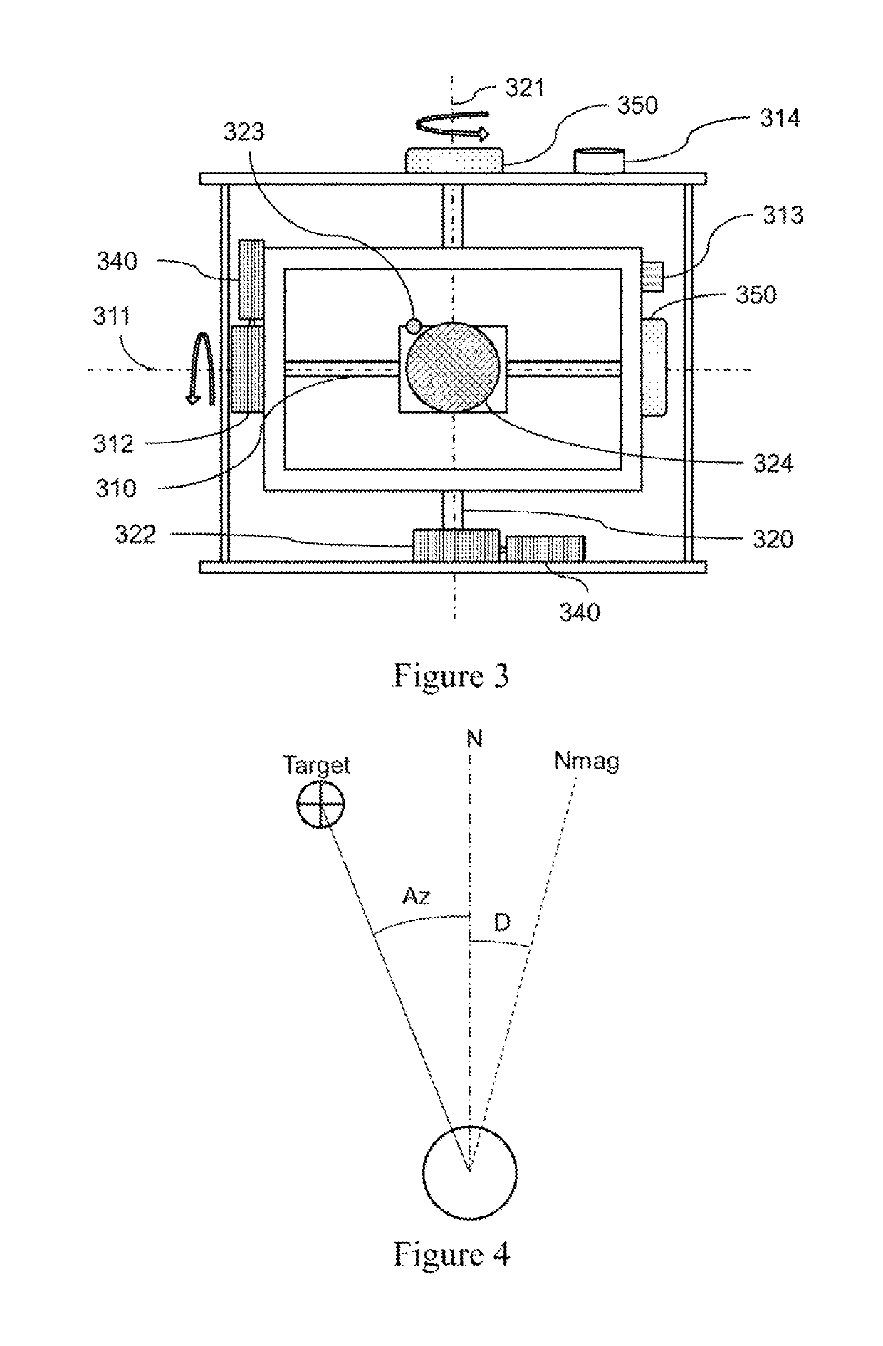
An autonomous magnetic observatory is provided that includes a scalar magnetometer for measuring the modulus of the local magnetic field vector F; an angular magnetometer for measuring the vertical direction, the direction of geographic North, and the direction of the local magnetic field vector F; a variometer for measuring three variations in the local magnetic field vector F; a clock; and a controller. In which observatory, the controller is configured to control and manage the orientation of sensors, to acquire the measurements of the variometer, of the scalar magnetometer, of the angular magnetometer and of the variometer, and to process the acquired measurements in order to obtain automatically, the local magnetic field vector F and the errors in the measurements associated with each instrument.

Description

TECHNICAL FIELD[0001]According to a first aspect, the invention relates to magnetic observatories (of the local terrestrial magnetic field) and more particularly to autonomous magnetic observatories.[0002]According to a second aspect, the invention relates to an automatic and self-calibrated method for obtaining the local (terrestrial) magnetic field vector.PRIOR ART[0003]A certain number of what are called autonomous magnetic observatories (of the local terrestrial magnetic field) already exist. In practice, these observatories are only partially autonomous. For example, the article “On the calibration of a vectorial 4He pumped magnetometer” by O. Gravrand, A. Khokhlov, J. L. Le Mouel, and J. M. Leger published in Earth Planets Space, 53, 949-958, 2001 discloses a vector magnetometer employing optically pumped helium vapor and a calibration method for this magnetometer. This magnetometer makes it possible to obtain an absolute measurement of the strength of the local magnetic field...

Claims


Application Information

Patent Timeline
Patent Type & Authority Applications(United States)
IPC IPC(8): G01C17/02G01R33/02G01V3/08
CPCG01C17/02G01R33/0206G01V3/08G01R33/02
Inventor RASSON, JEANGONSETTE, ALEXANDREHUMBLED, FRANCOIS
Owner INST ROYAL METEOROLOGIQUE DE BELGIQUE
Learn More