Planetary reduction gear ring gear for a turbine engine

a technology of planetary reduction and turbine engine, which is applied in the direction of gearing, machines/engines, hoisting equipment, etc., can solve the problems of reducing the efficiency of oil evacuation and difficulty in removing oil through the notches, and achieve the effect of preventing oil slippag

Active Publication Date: 2019-06-06
SAFRAN TRANSMISSION SYST
View PDF0 Cites 10 Cited by
  • Summary
  • Abstract
  • Description
  • Claims
  • Application Information

AI Technical Summary

Benefits of technology

[0013]The invention therefore proposes to limit, and even to prevent the slippage of oil onto the rims of the ring gear, by means of the retention walls. During operation, under the effect of centrifugal forces, the oil will tend to be prevented from turning with the ring gear and will be stored in pockets, each of which is delimited by adjacent walls. Ideally, each pocket will communicate with at least one crossing notch of the flanges, for the purpose of evacuating the oil outside the ring gear.

Problems solved by technology

One of the problems with this type of reduction gear is ensuring the proper lubrication of the meshing between the sun gear and the planet gears among themselves.
However, during operation, owing to the rotation of the ring gear, the oil tends to slip onto the rims supporting the flanges and it is then difficult to evacuate it through the notches.
This phenomenon lowers the efficiency of the evacuation of the oil, and can have numerous detrimental consequences, such as the recirculation of the oil, the heating of the oil and therefore potentially of the meshing, etc.

Method used


Image

  • Planetary reduction gear ring gear for a turbine engine
  • Planetary reduction gear ring gear for a turbine engine
  • Planetary reduction gear ring gear for a turbine engine

Examples


Embodiment Construction

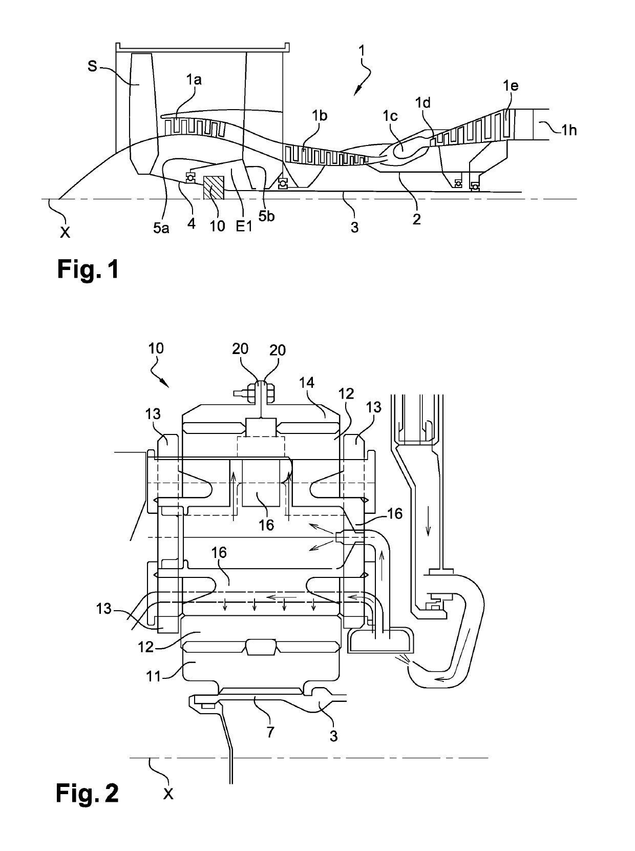
[0034]FIG. 1 shows a turbine engine 1 that comprises, conventionally, a propeller of a fan S, a low-pressure compressor 1a, a high-pressure compressor 1b, an annular combustion chamber 1c, a high-pressure turbine 1d, a low-pressure turbine 1e, and an exhaust pipe 1h. The high-pressure compressor 1b and the high-pressure turbine 1d are connected by a high-pressure shaft 2 and form with the latter a high-pressure (HP) body. The low-pressure compressor 1a and the low-pressure turbine 1e are connected by a low-pressure shaft 3 and form with the latter a low-pressure (BP) body.

[0035]The propeller of the fan S is driven by a fan shaft 4 coupled to the BP shaft 3 by means of a planetary reduction gear 10.

[0036]The reduction gear 10 is positioned in the front section of the turbine engine. A fixed structure comprising schematically, in this case, an upstream section 5a and a downstream section 5b is arranged to form an enclosure E1 around the reduction gear 10. This enclosure E1 is here clo...


PUM


Abstract

A planetary reduction gear ring gear for a turbine engine, in particular of an aircraft, the ring gear extending about an axis (X) and including first and second coaxial annular elements and respectively two inner annular teeth oriented differently. The first and second annular elements include respectively first and second radially external annular flanges to secure the first and second elements to one another, the teeth of the first and second annular elements being axially spaced from one another and from a joint plane (P) of the first and second flanges, and defining between them an annular space externally delimited by two annular rims supporting respectively the flanges. At least one of the flanges includes joint plane notches that are substantially radial for the oil to pass through by centrifugation. The ring gear further includes an annular row of oil-retention walls protruding from the rims in the space.

Description

FIELD OF THE INVENTION[0001]The present invention relates to the field of planetary reduction gears for turbine engines, in particular of an aircraft.STATE OF THE ART[0002]The state of the art comprises, in particular, documents FR-A1-2 853 382, FR-A1-2 942 284, FR-A1-2 987 402, FR-A1-2 987 416, FR-A1-2 987 417, FR-A1-3 041 054, FR-A1-3 047 279, US-A1-2014069743, EP-A1-2 644 939 and FR-A1-3 035 375.[0003]Current turbine engines, in particular turbine engines comprising one or several propellers generating a secondary flow, comprise a transmission system, called reduction gear, to drive the propeller(s) at an adequate rotational speed from the turbine shaft driving the primary body of the engine.[0004]The functioning of reduction gears, in particular in turbine engines provided with a fan propeller with an elevated dilution rate, requires a particularly high flow rate of oil to ensure the lubrication and cooling of their gears and bearings. The oil flow rate depends on the architectu...

Claims


Application Information

Patent Timeline
Patent Type & Authority Applications(United States)
IPC IPC(8): F16H57/04F16H55/17F16H57/08F16H1/28F02C7/36F01D25/18
CPCF16H57/0427F16H55/17F16H57/08F16H1/28F16H57/0486F02C7/36F01D25/18F16H2055/176F05D2260/40311F05D2260/98F16H57/0428F16H57/0482
Inventor CHARRIER, MATHIEU JEANMORELLI, BORIS PIERRE MARCELSIMON, ADRIEN LOUIS
Owner SAFRAN TRANSMISSION SYST
Why Eureka
Try Eureka