
Channel Driver Circuit

a driver circuit and channel technology, applied in the field of data communication systems, can solve problems such as adversely affecting user experien

Active Publication Date: 2019-06-06
SIGMASENSE LLC
View PDF0 Cites 31 Cited by
  • Summary
  • Abstract
  • Description
  • Claims
  • Application Information

AI Technical Summary

Benefits of technology

The patent text describes a system for collecting and processing sensor data. It includes a sensor that converts physical phenomena into electrical or optical signals, and a circuit that provides power and receives the sensor signal. The sensor circuit has at least three electrical connections to the sensor: one for power, another for a common voltage reference, and a third for receiving the sensor signal. The sensor circuits provide the received sensor signals to a computing device for processing. The technical effect of this invention is to improve the accuracy and reliability of sensor data collection and processing in various applications.

Problems solved by technology

The length of time to make a determination increases with the number of electrodes that must be measured, which may adversely affect user experience for relatively large displays that typically have a large number of electrodes to measure, relative to smaller projected capacitive (pCap) displays used in mobile devices.

Method used


Image

  • Channel Driver Circuit
  • Channel Driver Circuit
  • Channel Driver Circuit

Examples


embodiment 100

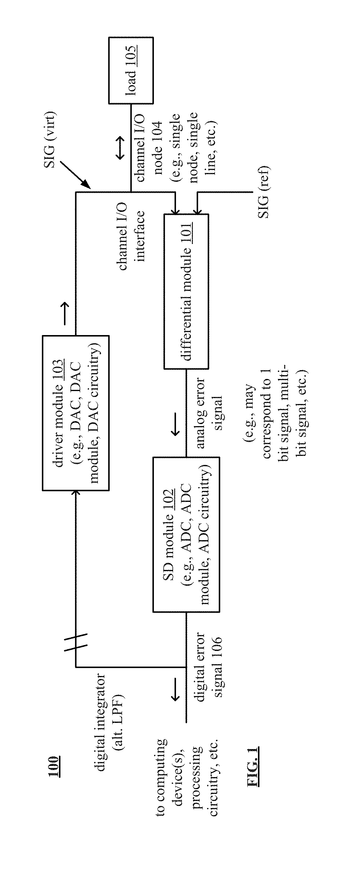
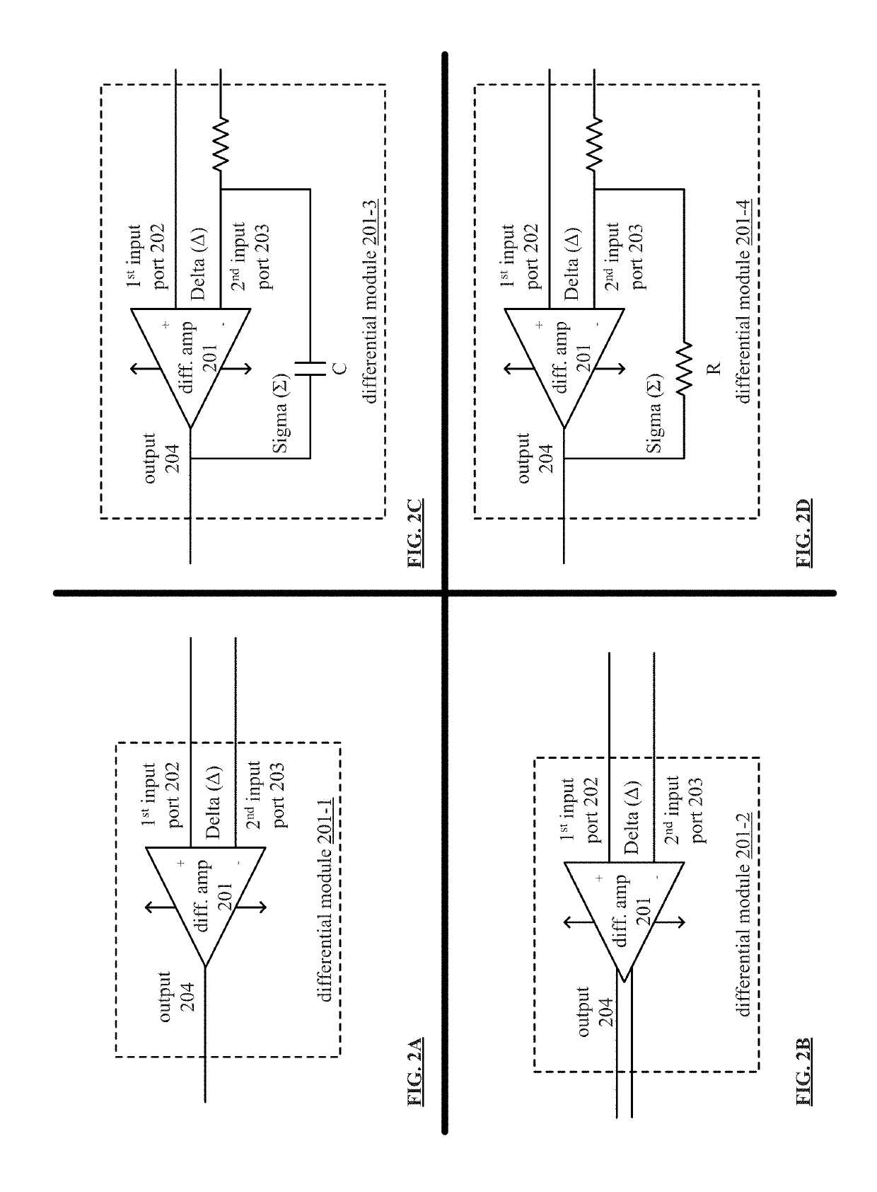
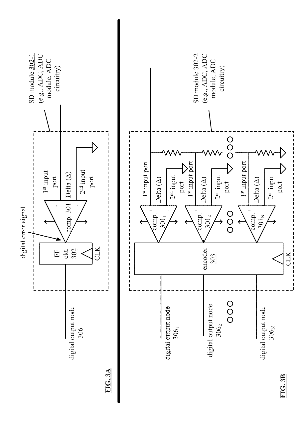
[0050]FIG. 1 is a schematic block diagram of an embodiment 100 of a channel driver circuit in accordance with the present invention. The channel driver circuit includes a differential module 101 coupled to a sigma-delta (SD) module 102. In some examples, note that the SD module 102 may be implemented as an analog to digital converter (ADC), an ADC module, ADC circuitry, etc. Note that the differential module 101 may be implemented as a differential amplifier that is configured to receive a signal reference (SIG (ref)) at one input. The channel driver circuit further includes a driver module 103 that forms an outer loop feedback from the output of the SD module 103 at a digital output node 106 to the differential module 101. In some examples, note that the driver module 103 may be implemented as a digital to analog converter (DAC), a DAC module, DAC circuitry, etc.

[0051]In some examples, the driver module 103 is configured to provide a variable power output to a channel input / output ...

embodiment 1000

[0120]FIG. 10 is a schematic block diagram of an embodiment 1000 of an AFE channel driver circuit coupled to a 1st order sigma-delta (SD) module in accordance with the present invention. Note that an ADC module such as described herein may be implemented in a variety of ways including using analog to digital or sigma-delta modulation techniques for conversion of the analog error signal to a digital form. This diagram illustrates an AFE channel driver circuit coupled to a SD module 1010 (e.g., which may be implemented as an ADC, ADC module, ADC circuitry, etc.) included of a 1nd order sigma-delta modulator circuit.

[0121]This diagram includes DAC module 1000 that includes a differential module 1021 coupled to SD module 1010 via a filter 1022, where the differential module 1001 includes a differential amplifier and is configured to receive a signal reference (SIG (ref)) at one input. The DAC module 1020 includes a driver module 1023 that forms an outer loop feedback from the output of ...


PUM


Abstract

A channel driver circuit includes a differential module and a driver module. In some examples, the channel driver circuit also includes a sigma-delta module. The differential module receives, via a single node of a load, a channel driving signal that is provided to the load at the single node (e.g., that is based on an electrical characteristic of the load) and generates an analog error signal that is based on the channel driving signal and a reference signal. The driver module is coupled to the differential module and generates the channel driving signal based on the analog error signal or a digital error signal corresponding to the analog error signal and transmits the channel driving signal via the single node to the load. The channel driver circuit simultaneously transmits the channel driving signal to the load at the single node and senses the channel driving signal at the single node.

Description

CROSS REFERENCE TO RELATED PATENTS[0001]The present U.S. Utility Patent Application claims priority pursuant to 35 U.S.C. § 119(e) to U.S. Provisional Application No. 62 / 620,812, entitled “CHANNEL DRIVER CIRCUIT,” filed Jan. 23, 2018, and U.S. Provisional Application No. 62 / 630,595, entitled “ANALOG FRONT END CHANNEL DRIVER CIRCUIT,” filed Feb. 14, 2018, all of which are hereby incorporated herein by reference in their entirety and made part of the present U.S. Utility Patent Application for all purposes.[0002]The present U.S. Utility Patent Application also claims priority pursuant to 35 U.S.C. § 120, as a continuation-in-part (CIP) of U.S. Utility patent application Ser. No. 16 / 109,600, entitled “MULTI-TOUCH SENSOR AND ELECTROSTATIC PEN DIGITIZING SYSTEM UTILIZING SIMULTANEOUS FUNCTIONS FOR IMPROVED PERFORMANCE,” filed Aug. 22, 2018, pending, which claims priority pursuant to 35 U.S.C. § 120 as a continuation of U.S. Utility application Ser. No. 15 / 506,097, entitled “MULTI-TOUCH S...

Claims


Application Information

Patent Timeline
Patent Type & Authority Applications(United States)
IPC IPC(8): G06F3/041H03M3/00G06F3/044G06F3/0354
CPCG06F3/0416H03M3/458G06F3/044G06F3/03545G06F2203/04104G06F3/0418G06F3/04162
Inventor GRAY, PATRICK TROYHUYNH, PHUONG
Owner SIGMASENSE LLC
Learn More