
Asteroid mining systems facilitated by cosmic ray and muon-catalyzed fusion

a technology of cosmic ray and muon, which is applied in the field of space systems, can solve the problems of inability to explore, large amount of fuel consumed, and limited methods being explored

Inactive Publication Date: 2019-06-06
DREXLER JEROME
View PDF6 Cites 3 Cited by
  • Summary
  • Abstract
  • Description
  • Claims
  • Application Information

AI Technical Summary

Benefits of technology

The present invention is about using deuterium-containing material to fuse with nuclear particles. This is done by using the natural flux of cosmic rays and generated muons. The concentration of the target material is optimized to produce enough electrical generation while avoiding any possibility of a runaway fusion event. The technical effect is the achievement of nuclear micro-fusion using deuterium-containing target material and the ambient flux of cosmic rays and generated muons.

Problems solved by technology

Because of the greater velocity change needed for redirecting an asteroid to a more convenient location for mining, the methods being explored would be limited at this time to asteroids smaller than about 20 m in diameter and with a mass not more than 107 kg.
But this consumes significant amounts of fuel and isn't feasible with current rocket technology.
Likewise, to provide a constant acceleration from thrust would require that rocket engines burn constantly over the entire flight, leading to even greater fuel usage.
Even when using a standard accelerate-coast-decelerate trajectory, an asteroid's heavy mass calls for a significant penalty in fuel if using chemical rocket engines.
The energy expense of generating muons artificially in particle accelerators combined with their short lifetimes has limited its viability as an Earth-based fusion source, since it falls short of break-even potential.
Although some fusion events can be observed with as little as 10 KeV acceleration, fusion cross-sections are sufficiently low that accelerator-based particle-target fusion are inefficient and fall short of break-even potential.

Method used


Image

  • Asteroid mining systems facilitated by cosmic ray and muon-catalyzed fusion
  • Asteroid mining systems facilitated by cosmic ray and muon-catalyzed fusion
  • Asteroid mining systems facilitated by cosmic ray and muon-catalyzed fusion

Examples


Embodiment Construction

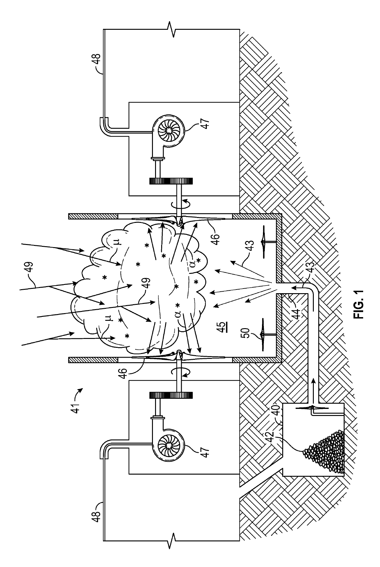
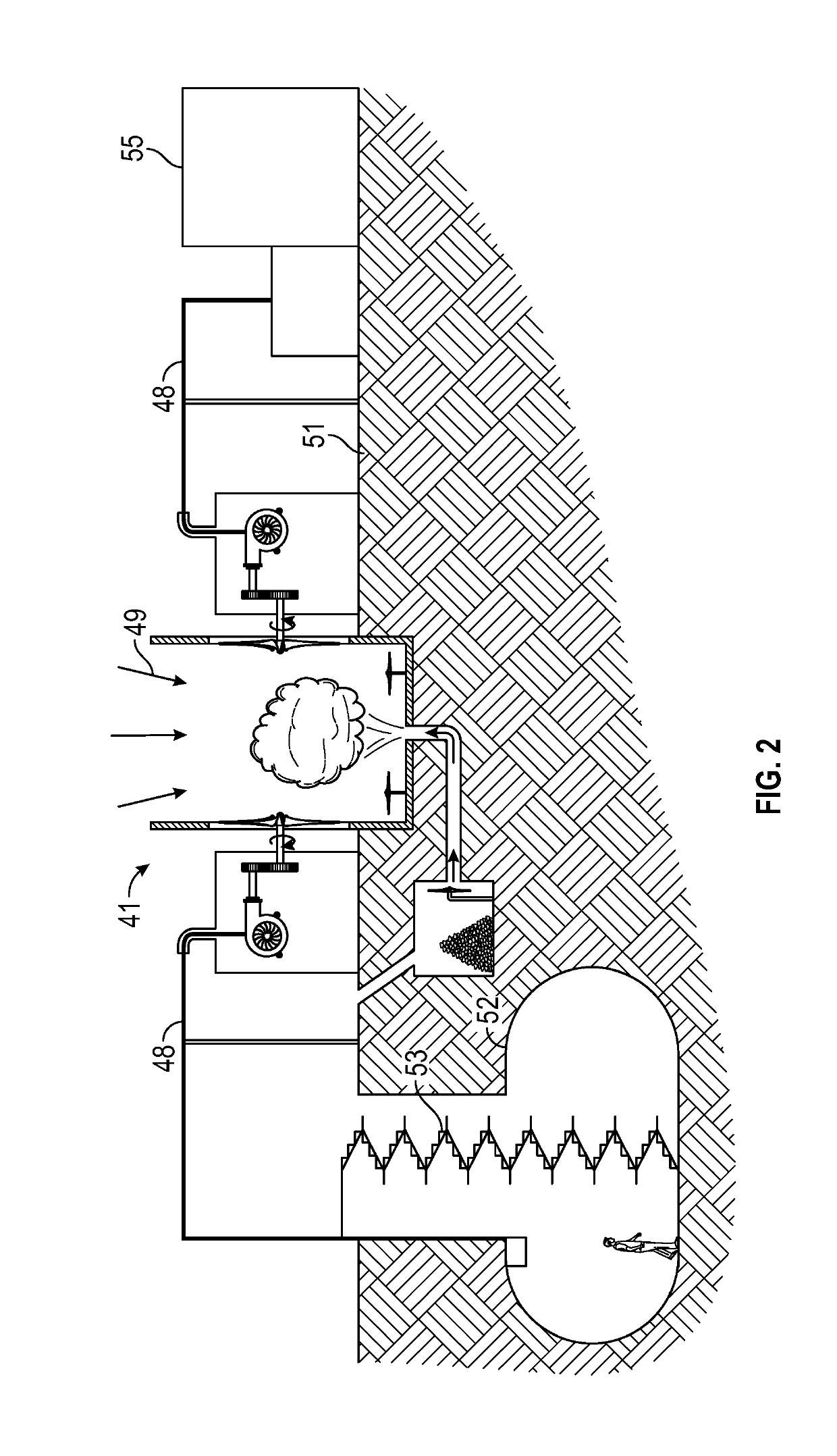
[0021]Cosmic-ray and muon-catalyzed micro-fusion can be employed in the invention to supply electrical power for mining of asteroids (either by automated mining equipment transported to the asteroid, or with assistance of astronaut-miners) and the mined products returned to Earth. Cosmic ray flux naturally present in interstellar space is used to power nuclear micro-fusion events (via particle-target micro-fusion and muon-catalyzed micro-fusion) that will generate electrical energy for the mining activity.

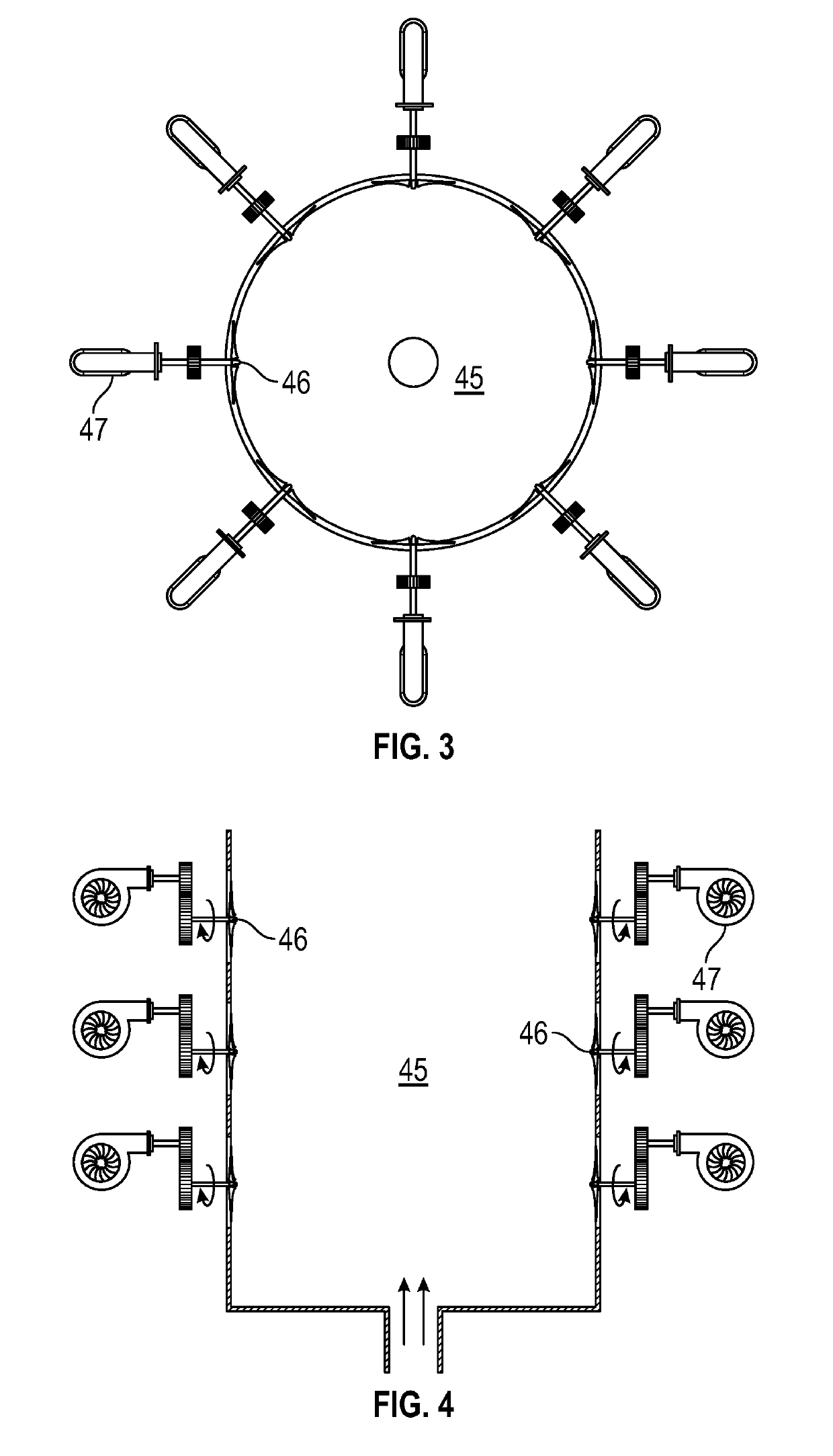
[0022]In the embodiment shown in FIG. 1, each engine may have one or more turbine electric generators 41, where the turbines are driven by the fast helium nuclei micro-fusion products generated from dispersed lithium-6 deuteride or other deuterium-containing micro-fusion target material exposed to the cosmic rays. Micro-fusion fuel packages would be delivered to the vicinity of each of the turbines, where the micro-fusion reaction products can turn the turbines to generate electric...


PUM


Abstract

Cosmic ray and muon-catalyzed micro-fusion electrical generation provides electrical power for mining operations, including any asteroid habitats and mining equipment. The micro-fusion generator systems deploy deuterium-containing fuel material as a localized cloud interacting with incoming ambient cosmic rays to generate energetic fusion products. Dust or other particulate matter in the fuel material, in the localized cloud, and in the space surrounding the asteroid being mined converts some cosmic rays into muons that also catalyze fusion. The fusion products drive turbines to facilitate the electrical generation.

Description

TECHNICAL FIELD[0001]The present invention relates to space systems that provide energy for asteroid mining operations in space (or on a lunar or planetary surface).BACKGROUND ART[0002]Many asteroids are rich in valuable elements that are either relatively rare in the Earth's crust or whose terrestrial reserves are becoming increasingly scarce due to overconsumption (e.g., the platinum-group metals, as well as nickel and cobalt). By one estimate, a 100 m diameter M-type asteroid may contain $50 billion worth of platinum. Additionally, many other asteroids comprise raw materials for space-based construction or as a source of extractable water and oxygen useful for sustaining manned deep space operations.[0003]Methods are being explored for redirecting small asteroids (less than 100 m diameter) into a new orbit to exploit its mineral resources more conveniently. Redirection techniques being explored generally divide into those that provide a large, but short-lived, impulse to the aste...

Claims


Application Information

Patent Timeline
Patent Type & Authority Applications(United States)
IPC IPC(8): G21D7/00F03D9/25B64G1/40B64G99/00G21H7/00G21D1/02G21B1/11G21B1/19
CPCG21D7/00F03D9/25B64G1/405B64G9/00G21H7/00G21D1/02G21B1/11G21B1/19E21C51/00G21Y2004/502G21B3/004B64G1/421B64G1/40B64G1/54Y02E10/72Y02E30/10Y02E30/00B64G99/00B64G1/413
Inventor DREXLER, JEROME
Owner DREXLER JEROME
Learn More