Battery pack structure of vehicle

Active Publication Date: 2019-06-06
HYUNDAI MOTOR CO LTD +1
View PDF18 Cites 0 Cited by
  • Summary
  • Abstract
  • Description
  • Claims
  • Application Information

AI Technical Summary

Benefits of technology

[0007]Various aspects of the present invention are directed to providing a structure which is optimized not in terms of increasing the loading capacity of battery cells, but in terms of the pack module of a battery system

Problems solved by technology

There is a method of increasing the loading capacity of cells to increase the energy density of a battery system, but it may be accompanied by package limit on a vehicle, an increase in weight and manufacturing cost, and a decrease in energy efficiency.
The structures of pack modules in the related art are simply increased only in size in the cell stacking direction, so excessive

Method used


Image

  • Battery pack structure of vehicle
  • Battery pack structure of vehicle
  • Battery pack structure of vehicle

Examples


Embodiment Construction

[0029]Reference will now be made in detail to various embodiments of the present invention(s), examples of which are illustrated in the accompanying drawings and described below. While the invention(s) will be described in conjunction with exemplary embodiments, it will be understood that the present description is not intended to limit the invention(s) to those exemplary embodiments. On the other hand, the invention(s) is / are intended to cover not only the exemplary embodiments, but also various alternatives, modifications, equivalents and other embodiments, which may be included within the spirit and scope of the invention as defined by the appended claims.

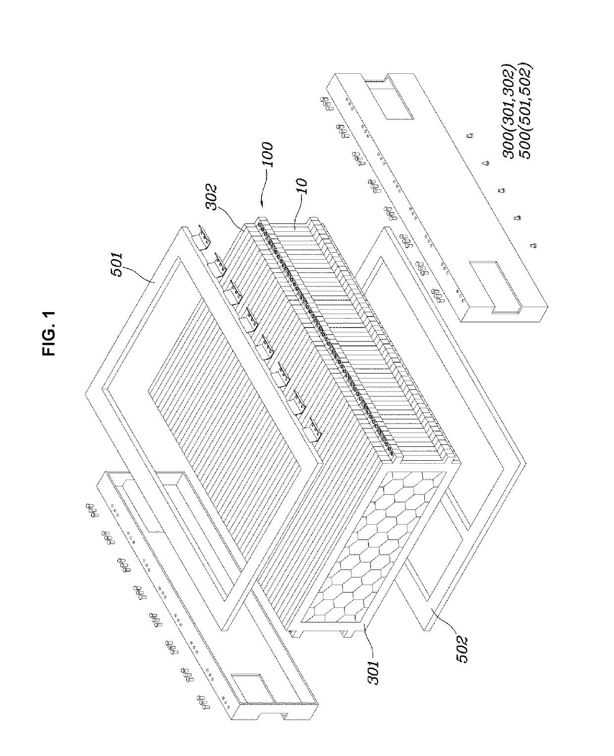
[0030]Hereinafter, a battery pack structure of a vehicle according to various embodiments is described with reference to the accompanying drawings.

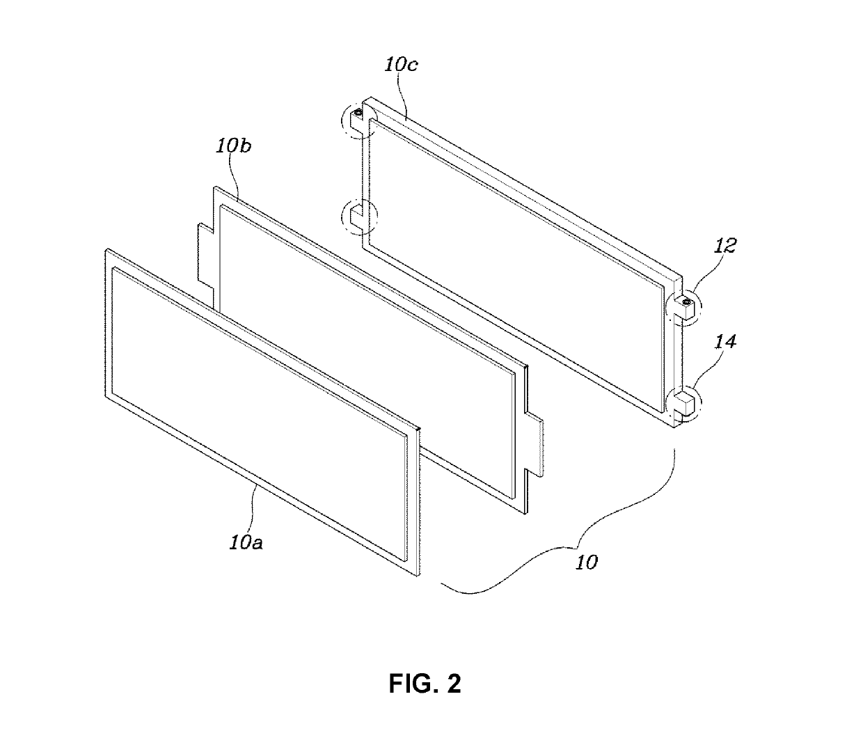
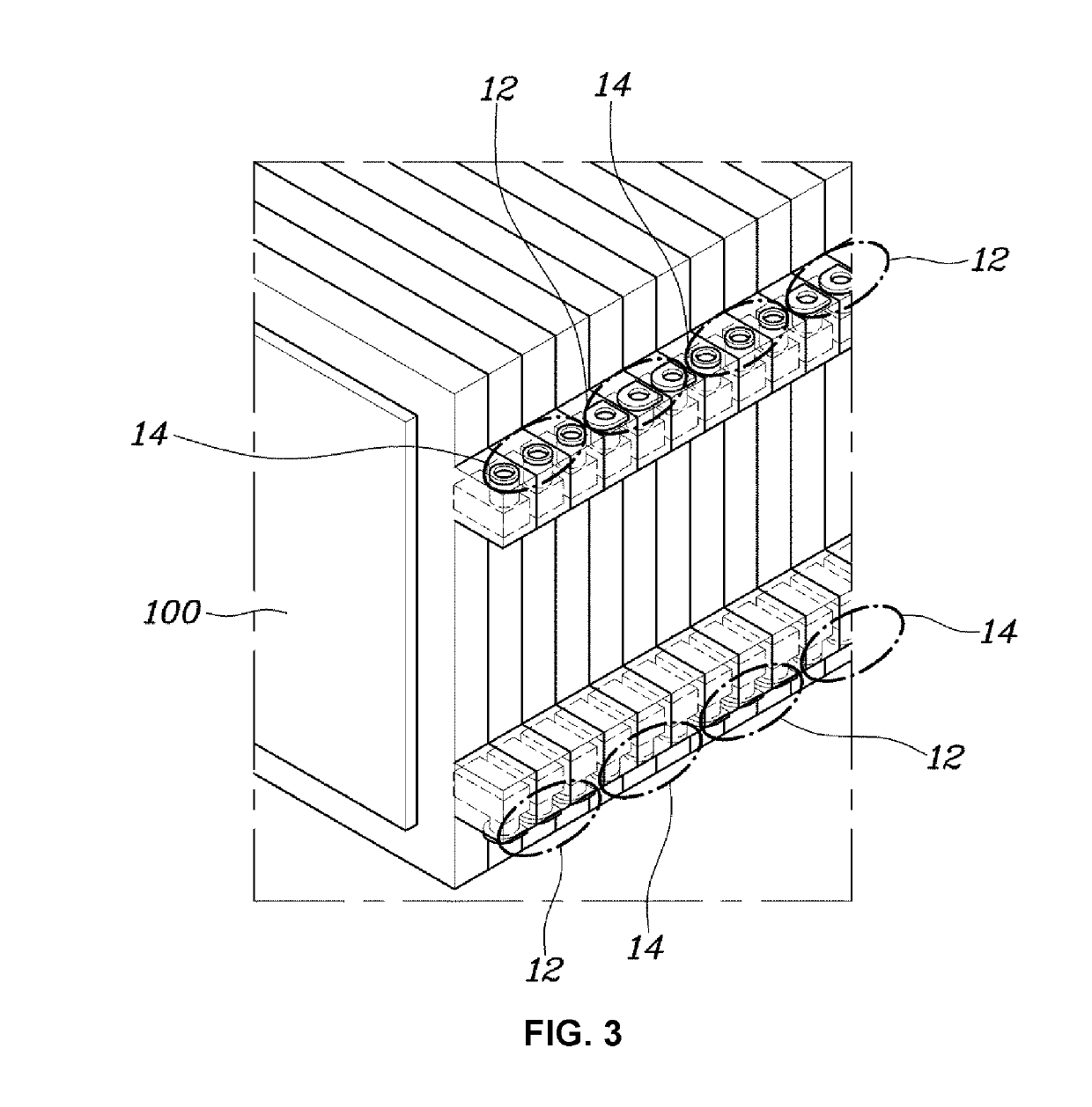
[0031]FIG. 1 is a view illustrating a battery pack structure of a vehicle according to various exemplary embodiments of the present invention, FIG. 2 is a view illustrating a cell mod...


PUM


Abstract

A battery pack structure of a vehicle, may include a cell module assembly formed by stacking a plurality of cell modules, end plates coupled to both side end portions of the cell module assembly, and support plates coupled to the top and the bottom of the cell module assembly and both side end portions of the end plates to bring the cell modules in contact with each other.

Description

CROSS-REFERENCE TO RELATED APPLICATION[0001]The present application claims priority to Korean Patent Application No. 10-2017-0166712, filed on Dec. 6, 2017 in the Korean Intellectual Property Office, the entire contents of which is incorporated herein for all purposes by this reference.BACKGROUND OF THE INVENTIONField of the Invention[0002]The present invention relates to a battery pack structure of a vehicle and, more particularly, to a battery pack structure of a vehicle, the battery pack structure having reduced weight and size due to improvement of the structure of the battery pack and being characterized by uniform distribution of surface pressure on cells by reducing differences among the cells due to increases in capacity and in the number of cells of a battery system.Description of Related Art[0003]High capacity and high power are required for high-voltage battery systems that are mounted on eco-friendly vehicles to satisfy needs of customers such as long mileage and high ze...

Claims


Application Information

Patent Timeline
IPC IPC(8): H01M2/10H01M2/30H01M2/20B60L11/18H01M50/202H01M50/211H01M50/262H01M50/296H01M50/505
CPCH01M2/1077H01M2/305B60L50/66H01M2/206H01M2220/20Y02T10/70Y02E60/10H01M50/202H01M50/296H01M50/505H01M50/262H01M50/211H01M50/502H01M50/249
Inventor KIM, MIN WOOKKWON, BEOM JOOJEON, YOON CHEOL
Owner HYUNDAI MOTOR CO LTD
Why Eureka
Try Eureka