Ice protection system and controller

a technology of ice protection system and controller, which is applied in the direction of machines/engines, mechanical equipment, transportation and packaging, etc., can solve the problems of affecting the configuration of the airfoil, affecting the airfoil, and increasing the weight of the structur

Active Publication Date: 2019-06-13
BATTELLE MEMORIAL INST
View PDF0 Cites 13 Cited by
  • Summary
  • Abstract
  • Description
  • Claims
  • Application Information

AI Technical Summary

Benefits of technology

[0020]In particular embodiments of the disclosed methods, one or more of sampling the temperature, determining an ideal setpoint temperature, determining a progressively adjusted setpoint temperature, generating a proportional drive signal, converting the proportional drive signal, and delivering the power output is performed by the controller of the ice-protection system.

Problems solved by technology

Aerodynamic surfaces, for example, wind turbines and airfoils, when exposed to atmospheric icing conditions are susceptible to ice build-up.
If not removed, this accumulated ice can add excessive weight to the structure, alter the airfoil configuration, and negatively impact performance.
Layers of ice can build up on the drone surfaces, dramatically affecting its aerodynamics and resulting in undesirable and / or dangerous flying performance.
Ice can also accumulate and then detach, where it may be ingested by the engine or cause other damage to the aircraft.
However, typical ice protection systems and controllers require integration with the structural composite of the aerodynamic structure and cannot be retrofitted to existing structures.
Furthermore, the location of the heaters far below the critical surfaces means that these systems require substantial power to effectively prevent ice accumulation or to remove existing ice layers.
At higher power densities, such as needed for icing conditions at temperatures below 0° F. and airspeeds of about 150 to about 180 knots, or where atmospheric conditions have a higher liquid water content, the heating elements may overheat during powering, which can cause degradation of the CNT-based heating device and / or the associated airfoil structure.
This can lead to catastrophic failure of the system and / or loss of structural integrity of the aircraft.
For example, the maximum operating temperature of some carbon fiber aircraft is below 145° F. Moreover, the CNT-based heating devices are capable of heating very rapidly, and therefore can easily become overheated and cause damage to the aircraft.
As a result, the potential demand on the drone's power source has increased while simultaneously reducing the available space for such systems, components, and power supplies.

Method used


Image

  • Ice protection system and controller
  • Ice protection system and controller
  • Ice protection system and controller

Examples


Embodiment Construction

[0038]One or more embodiments will now be described with reference to the attached drawings, wherein like reference numerals are used to refer to like elements throughout. Aspects of the exemplary embodiments related to ice protection systems and methods are described herein. However, application of the systems and methods set forth can be made to other areas utilizing an anti-icing or de-icing protection, or to heating of existing structures or materials.

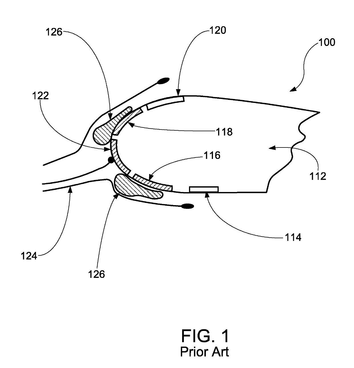
[0039]As used herein, the terms “aerodynamic structure” and “aerodynamic surface” refer to structures and surfaces over which a fluid flows. In particular, an aerodynamic structure or surface may refer to an aircraft, an airplane, a missile, an airfoil, or a portion thereof, such as a wing, a blade, an engine air inlet, or a nosecone.

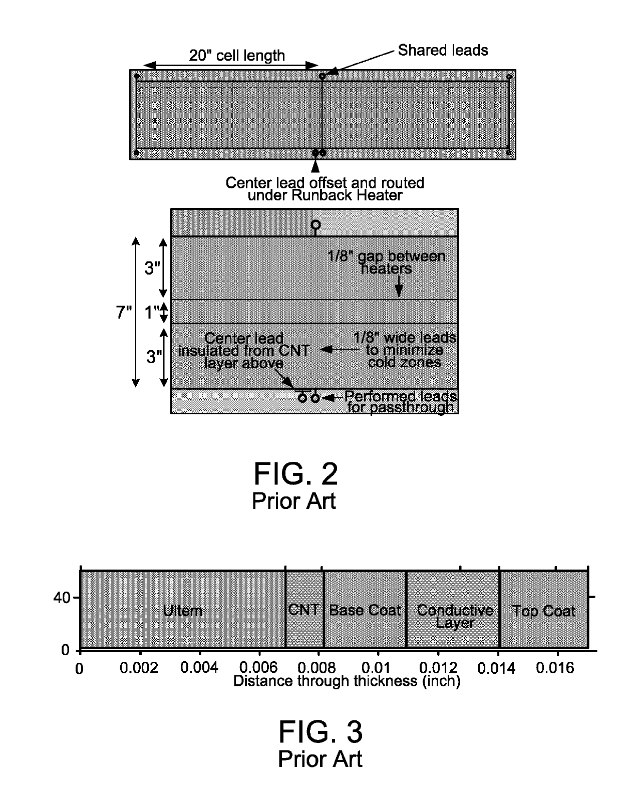
[0040]The term “carbon nanotube” or “CNT” includes single, double, and multiwall carbon nanotubes and, unless further specified, also includes bundles and other morphologies. The invention is not limit...


PUM


Abstract

An ice protection system and method capable of anti-icing and de-icing aerodynamic structures and surfaces is provided comprising a Resistive Heat Coat (RHC) controller and a heating device. The RHC controller comprises a RHC power circuit topology having a processor and a buck converter. The RHC controller further comprises a RHC control algorithm. The heating device comprises a plurality of resistive heating elements, such as CNT-based resistive heaters. The ice protection systems and methods disclosed can achieve an efficiency of 98% or greater while employing a direct current (DC) power supply and “hard switching” with a switching frequency of at least 500 kHz.

Description

CROSS-REFERENCE TO RELATED APPLICATIONS[0001]This application claims priority to U.S. Provisional Patent Application Ser. No. 62 / 578,666, filed Oct. 30, 2017, titled ICE PROTECTION SYSTEM AND CONTROLLER, the entire disclosure of which is incorporated by reference herein.BACKGROUND[0002]The following relates generally to ice protection systems and methods, de-icing and anti-icing systems and methods, aerodynamic structures equipped with ice protection, de-icing, and anti-icing systems, air vehicle arts, unmanned autonomous vehicle arts, electronic controller arts, and the like. It finds particular application in conjunction with high-efficiency ice protection systems in low-power applications. However, it will be understood that it also finds application in other usage scenarios and is not necessarily limited to the aforementioned applications.[0003]Aerodynamic surfaces, for example, wind turbines and airfoils, when exposed to atmospheric icing conditions are susceptible to ice build...

Claims


Application Information

Patent Timeline
Patent Type & Authority Applications(United States)
IPC IPC(8): B64D15/12H05B1/02H05B3/14H05B3/56F03D80/40
CPCB64D15/12H05B1/0236H05B3/145H05B3/565F03D80/40H05B2203/005H05B2203/035H05B3/34H05B2214/02H05B2214/04B64D15/14
Inventor BURTON, BRETTHOHE, DONALD R.HUNTWORK, MATTHEW E.STOUT, GABE J.
Owner BATTELLE MEMORIAL INST
Why Eureka
Try Eureka