
Dynamic road surface detecting method based on three-dimensional sensor

a three-dimensional sensor and dynamic technology, applied in the direction of instruments, measurement devices, using reradiation, etc., can solve the problems of inconclusive and meaningless distance comparison between mesh-based methods, less applicable to point clouds generated by low resolution lidar,

Active Publication Date: 2019-06-13
AUTOMOTIVE RES & TESTING CENT
View PDF1 Cites 35 Cited by
  • Summary
  • Abstract
  • Description
  • Claims
  • Application Information

AI Technical Summary

Benefits of technology

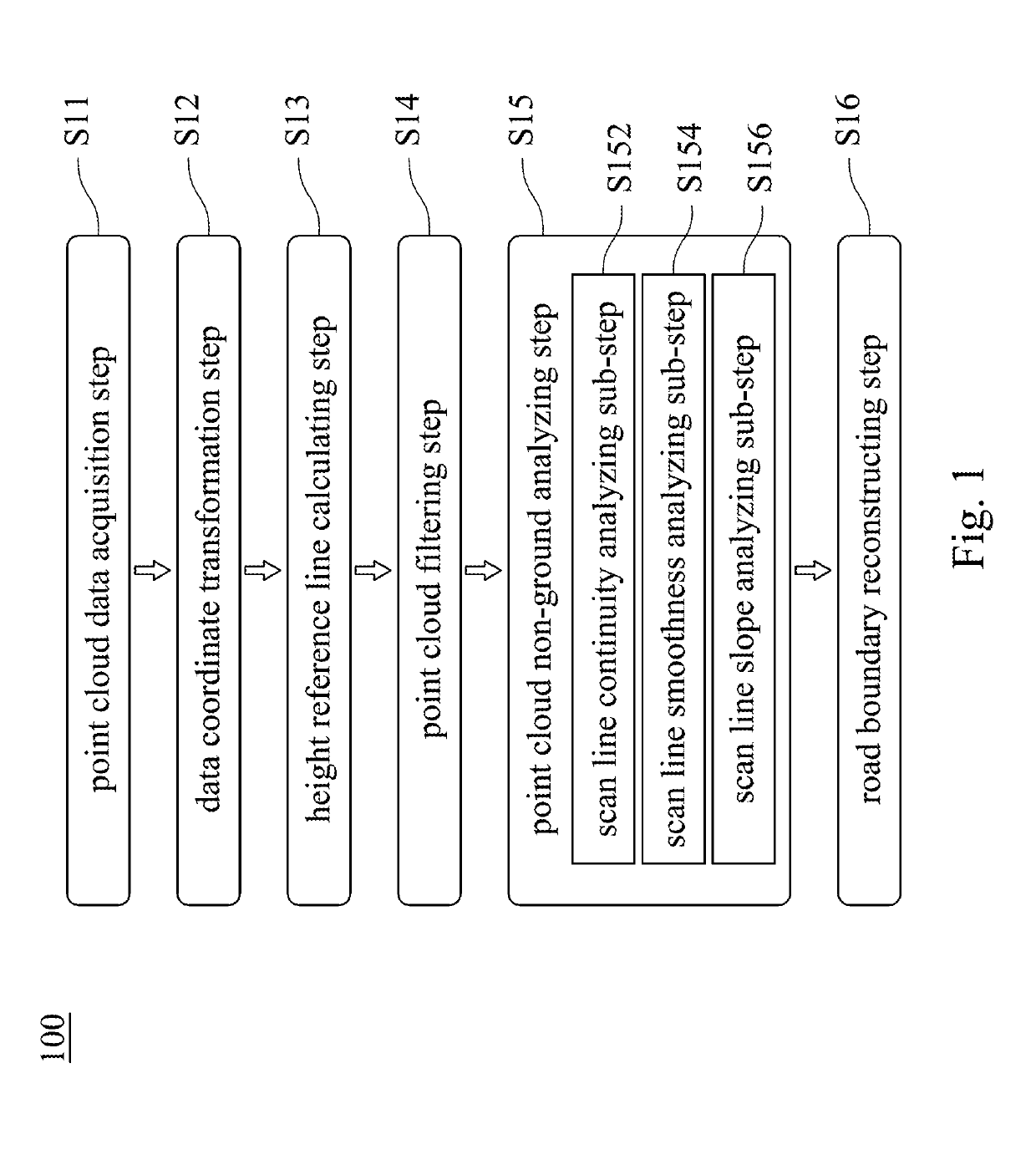
The present disclosure provides a method for detecting a dynamic road surface using a three-dimensional sensor on a vehicle. The method involves acquiring point cloud data, transforming the data to a vehicle coordinate system, calculating a height reference line, analyzing the data to identify discontinuous points, and linking the discontinuous points to reconstruct the road boundary. The method allows for accurate detection of the road surface and improved navigation for vehicles.

Problems solved by technology

In addition, the fact that vertically consecutive points are very likely to belong to completely distinct surfaces and different objects, which often makes the distance comparison between them inconclusive and meaningless.
In consequence, mesh-based methods are less applicable to the point cloud generated by low resolution lidar.
However, these layers are non-planar and have a distinct angle of incline, which makes their detection pattern different from one scan layer to another.
Moreover, as the planar assumption become invalid, ground detection methods used in 2D lidar do not apply to the individual scan layer.

Method used


Image

  • Dynamic road surface detecting method based on three-dimensional sensor
  • Dynamic road surface detecting method based on three-dimensional sensor
  • Dynamic road surface detecting method based on three-dimensional sensor

Examples


Embodiment Construction

[0025]Reference will now be made in detail to the present embodiments of the disclosure, examples of which are illustrated in the accompanying drawings. Wherever possible, the same reference numbers are used in the drawings and the description to refer to the same or like parts.

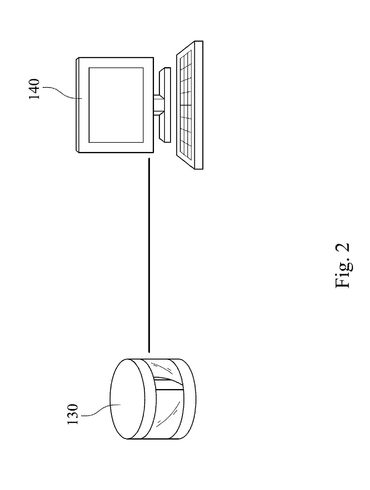
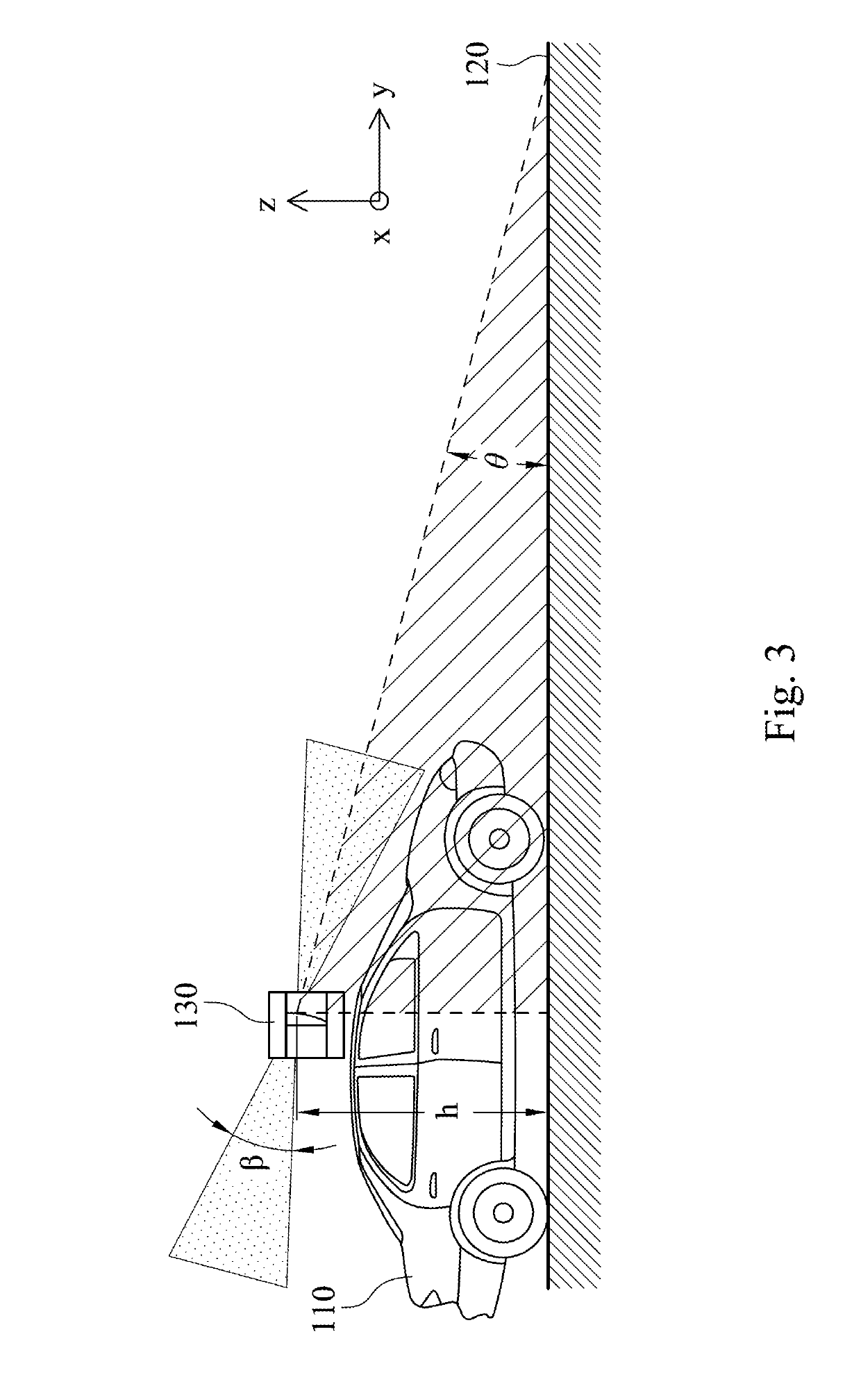
[0026]FIG. 1 shows a flow chart of a dynamic road surface detecting method 100 based on a three-dimensional sensor 130 according to one embodiment of the present disclosure; FIG. 2 shows a schematic view of a point cloud data acquisition step S11 of FIG. 1; FIG. 3 shows a schematic view of a data coordinate transformation step S12 of FIG. 1; FIG. 4A shows a schematic view of a height reference line calculating step S13 of FIG. 1; FIG. 4B shows a schematic view of a plurality of panes 200 of the height reference line calculating step S13 of FIG. 4A; FIG. 4C shows a schematic view of a road surface height reference line (xi,yi,zi) of the height reference line calculating step S13 of FIG. 4B; FIG. 5A shows a sch...


PUM


Abstract

A dynamic road surface detecting method based on a three-dimensional sensor is provided. The three-dimensional sensor receives a plurality of laser-emitting points reflected from a road surface to generate a plurality of three-dimensional sensor scan point coordinates which is transmitted to a point cloud processing module. The point cloud processing module transforms the three-dimensional sensor scan point coordinates to a plurality of vehicle scan point coordinates according to a coordinate translation equation, and then transforms a plurality of vehicle coordinate height values of the vehicle scan point coordinates to a road surface height reference line according to a folding line fitting algorithm. An absolute difference of two scan point height values of any two adjacent scan points on each of the scan lines is analyzed to generate a discontinuous point. The point cloud processing module links the discontinuous points to form a road boundary.

Description

RELATED APPLICATIONS[0001]This application claims priority to Taiwan Application Serial Number 106143402, filed Dec. 11, 2017, which is herein incorporated by reference.BACKGROUNDTechnical Field[0002]The present disclosure relates to a dynamic road surface detecting method. More particularly, the present disclosure relates to a dynamic road surface detecting method based on a three-dimensional sensor.Description of Related Art[0003]In autonomous driving sensing, it is important to build a reliable perception of the surrounding environment, and conduct precise detection of objects and free road space. Among many proposed approaches satisfying the requirements above, the use of lidar sensor has been proven reliable for its high resolution and precision. With high-frequency laser pulse emission-reception, lidar measures the distance between the sensor and the target points. A 3D lidar combine a rotational device with laser modules to obtain a 3D depth map within its vertical field of v...

Claims


Application Information

Patent Timeline
IPC IPC(8): G01S7/48G01S17/89
CPCG01S7/4802G01S17/89G01S17/42
Inventor TSAI, YI-SHUEHWANG, YU-FANG
Owner AUTOMOTIVE RES & TESTING CENT
Learn More