Receptacle connector equipped with cable instead of mounting to PCB

a technology of receptacle connectors and connectors, which is applied in the direction of coupling device connections, printed circuit aspects, coupling device details, etc., can solve the problems of heat dissipation of the lower level receptacle connector, difficulty in fine tuning for signal integrity, and through holes in printed circuit boards

Active Publication Date: 2019-06-13
FOXCONN (KUNSHAN) COMPUTER CONNECTOR CO LTD +1
View PDF0 Cites 9 Cited by
  • Summary
  • Abstract
  • Description
  • Claims
  • Application Information

AI Technical Summary

Benefits of technology

[0005]The contact module includes an upper subassembly and a lower subassembly stacked with each other in a mirror image arrangement oppositely. Each of the upper subassembly and the lower subassembly includes a front wafer and a rear wafer stacked together. Each of the front wafer and the rear wafer includes an insulator and a plurality of contacts integrally formed therein. A grounding plate is associated with the corresponding wafer for electrically integrally connecting all the grounding contacts thereof. The contacts include a plurality of low speed signal contacts at a center region, a plurality of differential pair signal contacts and a plurality of grounding contacts alternately arrange with each other by two sides of said low speed signal contacts in a transverse direction. All grounding contacts unitarily extend from a common grounding bar on which the outer braiding of each differential pair wires regulated and associated with a common grounding bracket is attached. The contacting section of the differential pair signal contacts of the front wafer are located in front of those of the rear wafer and both are aligned with each other in the front-to-back direction. The connecting sections of the differential pair signal contacts of the front wafer are located in front of those of the rear wafer while arranged in an offset manner in the transverse direction for allowing the corresponding differential pair wires connected with the connecting sections of the differential pair signal contacts of the front wafer to extend through the space between the two neighboring differential pair signal contacts without interference.

Problems solved by technology

Anyhow, several disadvantages exist for the traditional design.
Firstly, most receptacle connectors are of the horizontal right angle type, making it difficult to fine tune for signal integrity.
Secondly, most of them are of surface mounting type with the problems of coplanarity of the tails of all seventy-six contacts.
The manufacturing of such densely arranged through holes in the printed circuit board is another challenge.
Fourthly, in the stacked receptacle connectors, the heat dissipation for the lower level receptacle connector is another problem because the contacts of both the upper level connector and those of the lower level connector are required to extend downwardly toward the printed circuit board on which the lower level connector is mounted, and the cooling air essentially has less capability of passing therethrough along the front-to-back direction.

Method used


Image

  • Receptacle connector equipped with cable instead of mounting to PCB
  • Receptacle connector equipped with cable instead of mounting to PCB
  • Receptacle connector equipped with cable instead of mounting to PCB

Examples


Embodiment Construction

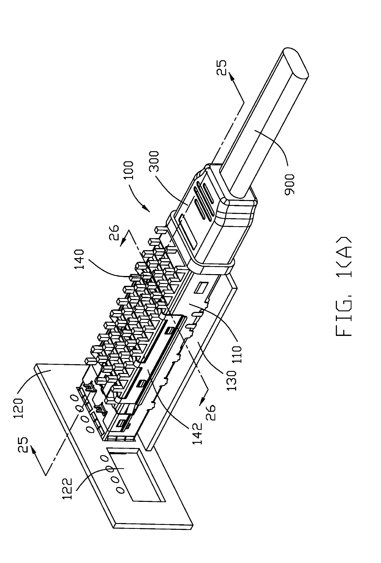
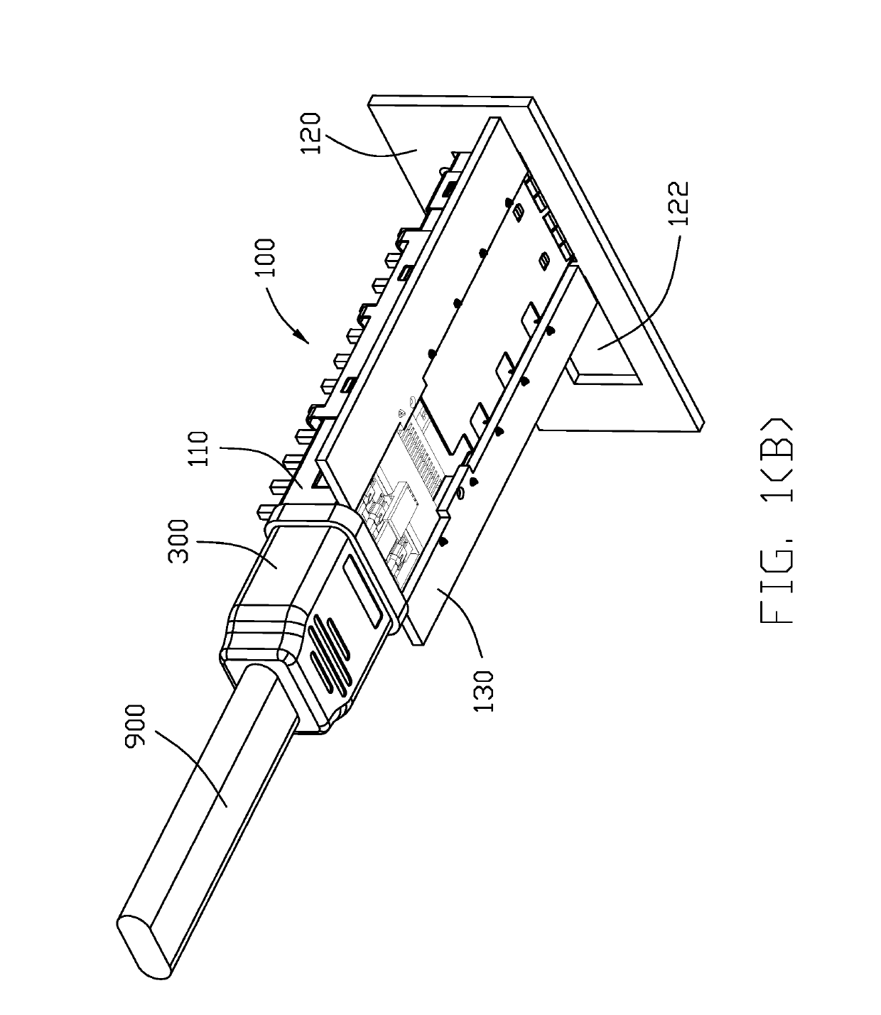
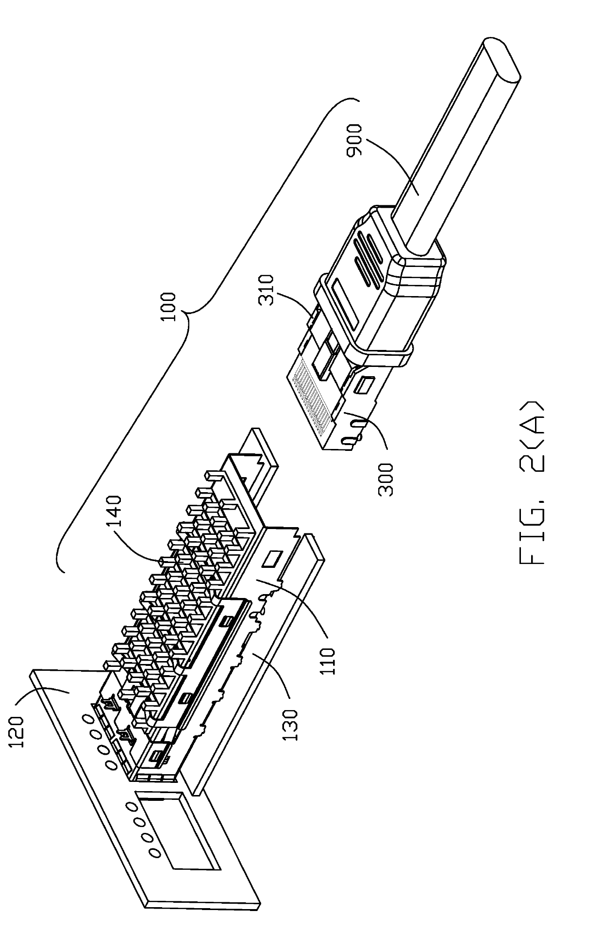
[0065]Reference will now be made in detail to the preferred embodiment of the present invention. Referring to FIGS. 1(A) to 6(B), an electrical system 100 includes a metallic cage or cage 110 located behind an opening 122 of a panel 120 and secured to a chassis 130 via the mounting lugs 112 through corresponding holes 132. The metallic cage 110 includes an opening 114 in the corresponding top wall 116. A heat sink 140 is attached upon the top wall 116 by a clip 142 so as to contact the QSFP plug module (not shown) which is received in the receiving space 118 of the cage 110 under the top wall 116. The chassis 130 further forms through holes 134 for receiving the corresponding mounting posts of a receptacle connector assembly 300 illustrated later.

[0066]Further referring to FIGS. 7(A)-25, a receptacle connector assembly 300 is received within a rear portion of the receiving space 118. The receptacle connector assembly 300 includes a receptacle connector 310 and the associated cables ...


PUM


Abstract

A QSFP-DD receptacle connector received within a cage includes an insulative housing and a contact module assembly received within the housing. The contact module includes a plurality of horizontal wafers stacked with one another, and each wafer includes an insulator and a plurality of contacts integrally formed therein wherein each contact has a front contact sections extending forwardly into a mating cavity formed in the housing, and a rear connecting section connected to a cable rather than to the printed circuit board. The receptacle connector associated with a cable is attached to a chassis. The cage optionally forms therein two mating spaces respectively receiving two receptacle connectors with the associated cables extending rearwardly.

Description

BACKGROUND OF THE INVENTION1. Field of the Invention[0001]The present invention relates to an electrical connector assembly, especially to the electrical connection with the external pluggable module via a dual-sided receptacle connector or a directly attached receptacle connector linked to an adaptor cable assembly by following the spirit of the previous designs of which the provisional applications have corresponding Ser. Nos. 62 / 367,098 filed on Jul. 26, 2016, 62 / 399,272 filed on Sep. 23, 2016, 62 / 412,841 filed on Oct. 26, 2016, 62 / 425,627 filed on Nov. 23, 2016, 62 / 449,133 filed on Jan. 23, 2017, 62 / 509,141 filed on May 21, 2017, 62 / 522,113 filed on Jun. 20, 2017, 62 / 533,131 filed on Jul. 17, 2017, and 62 / 584,751 filed on Nov. 11, 2017.2. Description of Related Art[0002]The traditional design used for connecting two sub-systems is mad through a QSFP (Quad Small Form-factor Pluggable) receptacle connector located in a cage and mounted upon a printed circuit board. Anyhow, several...

Claims


Application Information

Patent Timeline
Patent Type & Authority Applications(United States)
IPC IPC(8): H01R13/6587H01R13/6471H01R13/6593H05K1/02
CPCH01R13/6587H01R13/6471H01R13/6593H05K1/0243H05K2201/10189H05K2201/10356H01R13/6585
Inventor LITTLE, TERRANCE F.
Owner FOXCONN (KUNSHAN) COMPUTER CONNECTOR CO LTD
Why Eureka
Try Eureka