Technology for the Decentralized Storage of Energy

Inactive Publication Date: 2019-06-13
I SELECT SA
View PDF0 Cites 0 Cited by
  • Summary
  • Abstract
  • Description
  • Claims
  • Application Information

AI Technical Summary

Benefits of technology

The patent describes a system for storing heat using a latent heat storage device, which can be a salt hydrate like sodium acetate trihydrate. This system can be used in homes, buildings, or industrial installations to store excess energy in a flexible and decentralized way. The system is connected to a central power generation facility through a shared power grid, allowing for the distribution of excess energy across multiple heat storage devices. This setup is robust against failure and provides a flexible way to manage energy demand and supply.

Problems solved by technology

When energy production peaks occur, there may be a considerable amount of excess energy, which is not immediately consumed by the end users.

Method used


Image

  • Technology for the Decentralized Storage of Energy
  • Technology for the Decentralized Storage of Energy
  • Technology for the Decentralized Storage of Energy

Examples


Embodiment Construction

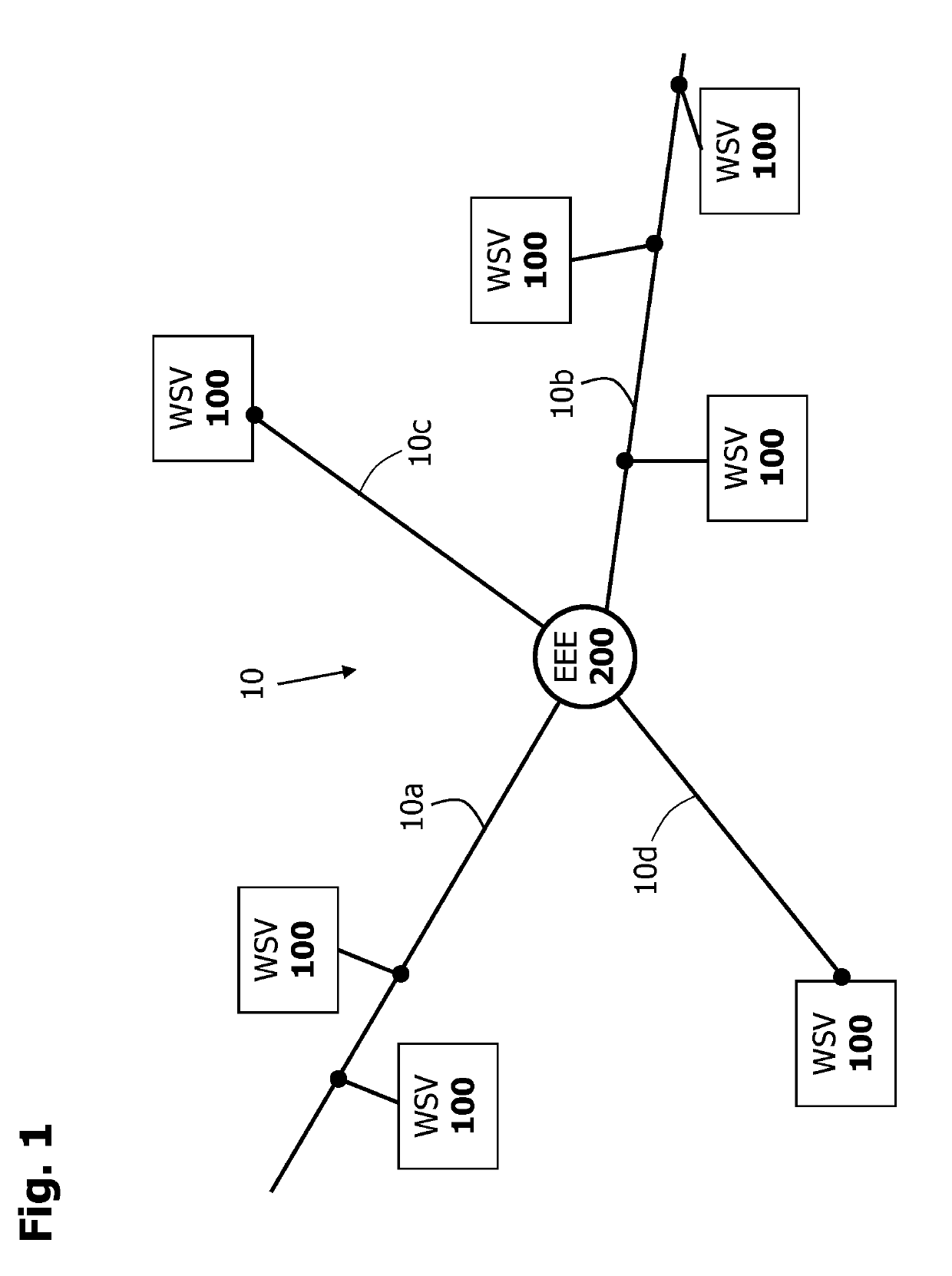
[0031]The present invention for the decentralized storage of energy will be further described in connection with FIG. 1. FIG. 1 shows a section of a conventional power grid 10 (or integrated grid) comprising a plurality of electrical power lines 10a-10d configured for the transmission of electrical energy. At least one centrally arranged energy generation facility 200 (abbreviated as “EEE” in FIG. 1) and a plurality of heat storage devices 100 (abbreviated as “WSV” in FIG. 1) are electrically coupled to the power grid 10. The heat storage devices 100 are arranged decentrally with respect to the at least one energy generation facility. They are arranged in or near an end user (not shown in FIG. 1), such as a private or public building, factories, or other facilities.

[0032]The energy generation facility 200 may be a conventional power plant or a renewable energy source, such as, for example, a wind farm (offshore or onshore wind farm) or a large-scale photovoltaic system. The power ge...


PUM


Abstract

A method for the decentralized storage of energy, wherein the energy is provided by at least one centrally arranged energy generation device for generating electrical energy includes providing at least one heat storage device that is decentrally arranged with respect to energy generation facility and electrically coupled to an energy generation facility; receiving a signal, provided by the energy generation facility, by at least one heat storage device, the signal indicating the presence of excess electrical energy at the energy generation facility; detecting the current discharge state of heat storage device; and, in response to the received signal and the detected discharge state, storing at least a portion of the excess electrical energy in the form of latent heat in the heat storage device. Further provided are a heat storage device and a system comprising a plurality of heat storage devices for implementing the above method.

Description

TECHNICAL FIELD[0001]The invention relates to the field of energy storage. Specifically, there is described a technology for decentrally storing energy provided by at least one centrally arranged energy generation facility for generating electrical energy.BACKGROUND[0002]Renewable energy sources, such as, for example, photovoltaic systems or wind turbines are increasingly gaining in importance. They are gradually replacing conventional power plants, such as nuclear power plants or thermal power plants, which rely on burning fossil energy sources. Conventional power plants have the advantage that they can produce a desired amount of electrical energy at any time (i.e. regardless of the time of day or season) and feed it into a power grid. In conventional power plants, the generation and supply of electrical energy into the power grid takes place on demand. To be able to provide sufficient electrical energy to end consumers at any time, reliable predictive models are needed that can p...

Claims


Application Information

Patent Timeline
IPC IPC(8): H02J3/28H02J3/38F28D20/02
CPCH02J3/28H02J3/386H02J3/383F28D20/028F24D11/00F28D20/00H02J15/00H02J3/00Y02P90/50Y02B10/20Y02E10/56Y02E10/76Y02E60/14
Inventor MUHR, CHRISTIAN
Owner I SELECT SA
Why Eureka
Try Eureka