Musical beat detection system and method for lighting control

a music beat and detection system technology, applied in the field of music beat detection system and lighting control, can solve the problems of insufficient affectiveness of existing products for their desired purpose, high cost of performance products that are effective, and relatively expensive low-pass filtering for extracting low frequency audio signals, etc., to achieve high performance and visual attractive

Active Publication Date: 2019-06-13
FOUSR GROUP
View PDF1 Cites 6 Cited by
  • Summary
  • Abstract
  • Description
  • Claims
  • Application Information

AI Technical Summary

Benefits of technology

[0009]In accordance with one aspect of the present invention, there is provided a circuit or device for causing a light source or object to flash in correspondence with certain sound signals received, such as the peak amplitude of a received sound signal. The circuit comprises a sensitive sound input microphone and a two-stage pre-amplifier, a microcomputer unit (MCU), an LED driver, and an array of LED lights. With the beat detection system of the present invention that enables lighting control of an illuminated object, there is provided a low-cost sound-activated lighting concept that is characterized by high-performance and that is visually attractive.

Problems solved by technology

One of the reasons why a consumer grade sound-activated light string is not widely available in the market is that the existing products are not affective enough for their desired purpose.
Furthermore performance products that are effective usually come at a high cost and are thus only suitable for professional or commercial usage.
In existing systems, a relatively expensive low-pass filter is needed to extract the low frequency audio signal.
This requires a relatively powerful and expensive microcomputer unit (MCU).
Some systems that use a microphone as input can only work for loud music.
Some systems using sensitive microphones can work with low volume music but when the volume is high they do not work properly.

Method used


Image

  • Musical beat detection system and method for lighting control
  • Musical beat detection system and method for lighting control
  • Musical beat detection system and method for lighting control

Examples


Embodiment Construction

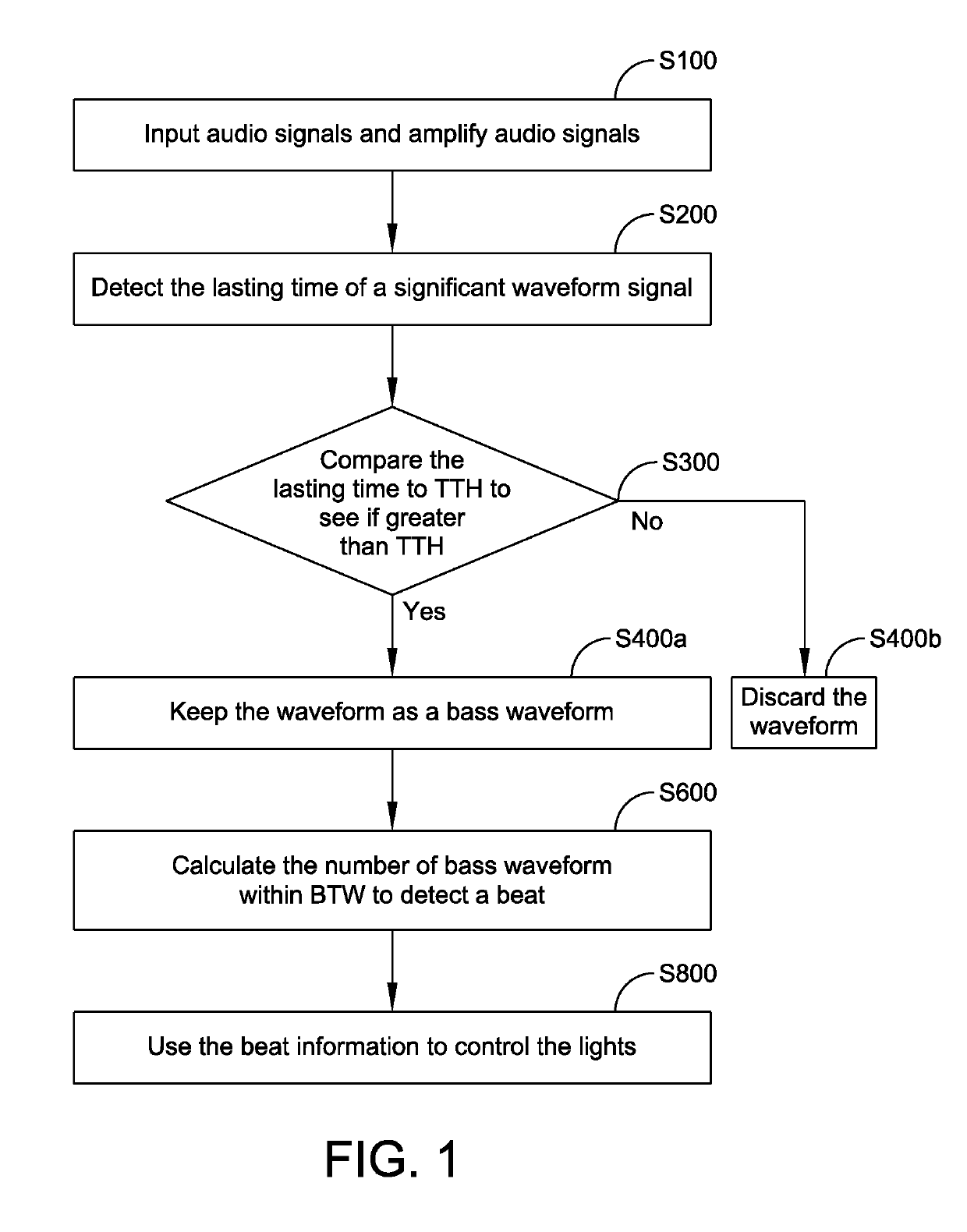
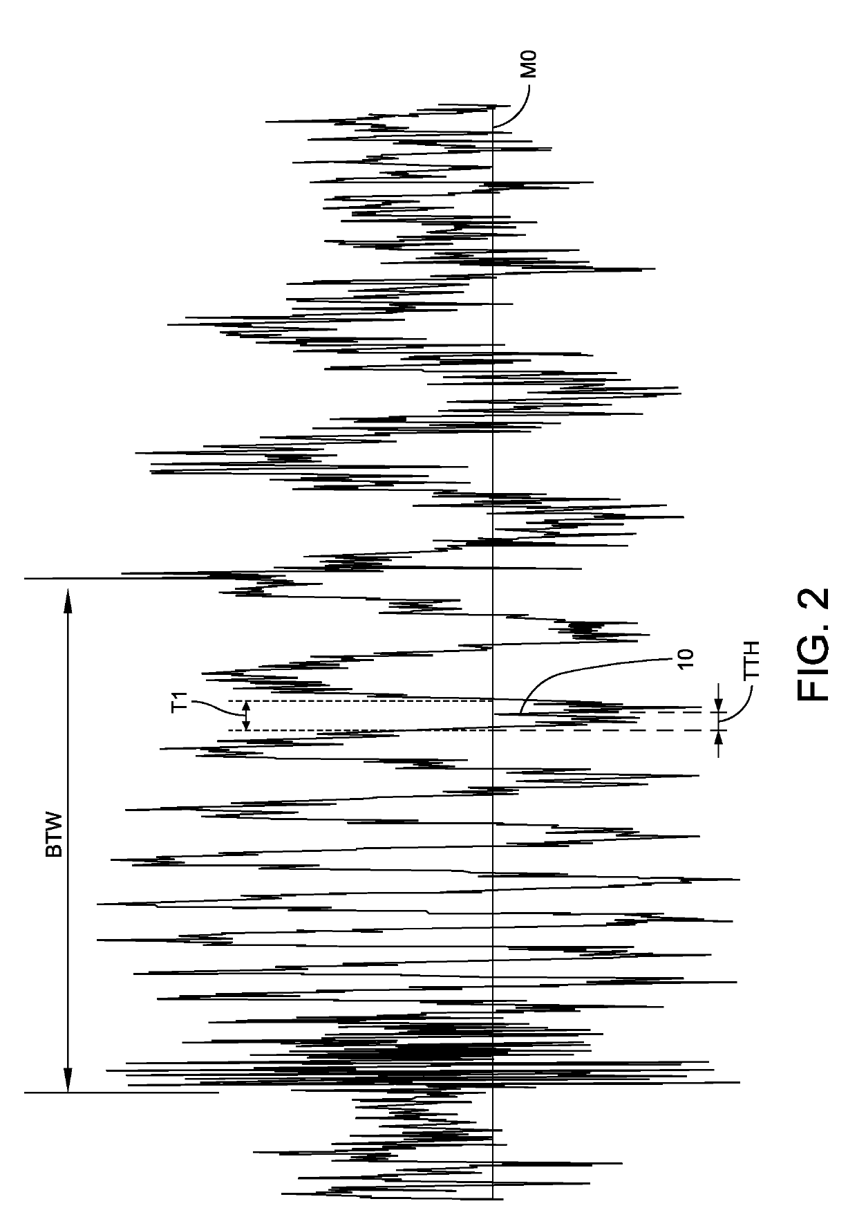
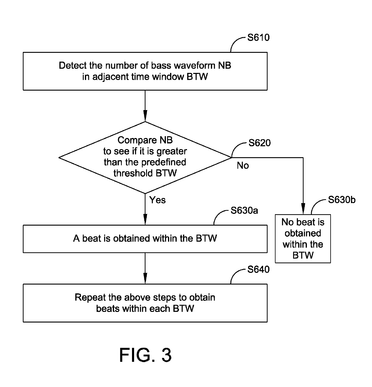
[0049]Reference is now made to all the figures used in describing the method and system of the present invention. In this regard, FIG. 1 is a general block diagram and flow chart that describe algorithms of the present invention. FIG. 2 is an audio signal waveform of one of the steps indicated in FIG. 1 and that is helpful in understanding the concepts of the present invention as it relates to the time window (BTW). FIG. 3 is a more detailed block diagram and flow chart related to one of the steps illustrated in FIG. 1. FIG. 4 is an audio signal waveform of one of the steps indicated in FIG. 1 indicating that there is a beat in the first BTW interval, while there is no beat in the second BTW interval. FIG. 5 is a somewhat more detailed block diagram and flow chart showing that, after detecting if a beat exists within each BTW interval, the tempo is calculated and used for adjustment in a certain range. FIG. 6 is a further block diagram and flow chart showing further details of the b...


PUM


Abstract

A system for controlling a plurality of light sources particularly LED's that are provided in a number of different arrangements including a light string and controlled from a controller that includes an input microphone for detecting an audio signal, at least one pre-amplifier, a microcomputer unit receiving signals from the pre-amplifier, and a circuit for driving a plurality of LED and that enables lighting control of the plurality of LED's in accordance with the input audio signal and within a wide dynamic range.

Description

RELATED CASES[0001]Priority for this application is hereby claimed under 35 U.S.C. § 119(e) to commonly owned and co-pending U.S. Provisional Patent Application No. 62 / 609,442 which was filed on Dec. 22, 2017 and which is incorporated by reference herein in its entirety.FIELD OF THE INVENTION[0002]The present invention relates in general to an apparatus or device for analyzing the beats of music in a musical piece in order to control a lighted or illuminated object. More particularly, the present invention relates to a novel musical beat detection system that enables lighting control within a wide dynamic range. The present invention also relates to a beat detection system that enables lighting control of an illuminated object and that can be implemented quite inexpensively with little or no complexity. The present invention still further relates to a beat detection system that enables lighting control of an illuminated object, and in which the object has a wide variety of uses such...

Claims


Application Information

Patent Timeline
Patent Type & Authority Applications(United States)
IPC IPC(8): H05B37/02G10L25/51H05B33/08H03F3/183H03F3/68H05B44/00
CPCH05B37/0236G10L25/51H05B33/0854H03F3/183H03F3/68G10H2210/076H03F2200/03H03F2200/267H05B45/10H05B47/12
Inventor ZHANG, MICHAEL WEIBIN
Owner FOUSR GROUP
Why Eureka
Try Eureka